


Vistek V1636 24-bit Audio Digital
To Analog Converter
Issue 4.0
11
3.2.3
A/B Swap
·
A transposition of AES A and AES B inputs may be invoked and the present
setting may be seen on the character display as a letter combination when
Page
0
Panel Adjustment mode has been entered and
A/B Swap
selected as a
parameter.
·
When AES input channelpairs A and B are normally converted to AL/AR and
BL/BR analog output pairs respectively, the A/B Swap parameter is indicated on
the character display as
A-A
.
·
When AES input channelpairs are transposed so that AES A converts to BL/BR
and AES B converts to AL/AR analog output pairs respectively, the A/B Swap
parameter is indicated on the character display as
A-b
.
3.2.4
Test Tone
·
A test tone of 997Hz 0dBu may be invoked on the L/R channels of either or both A
and B channelpair outputs and the present setting may be seen on the character
display as a number combination when
Page 1
Panel Adjustment mode has been
entered and
Test Tone
selected as a parameter.
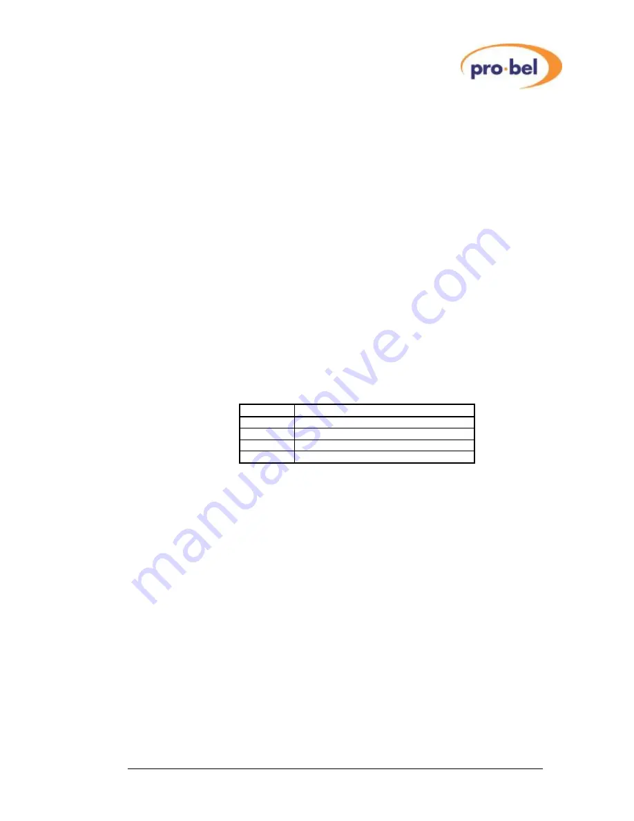
·
The table below explains the available Test Tone selections
Display
Test Tones
0 0
No test tones selected
1 0
Test tone on channelpair A only
0 1
Test tone on channelpair B only
1 1
Test tone on both channelpairs