


7
2.2 Connections
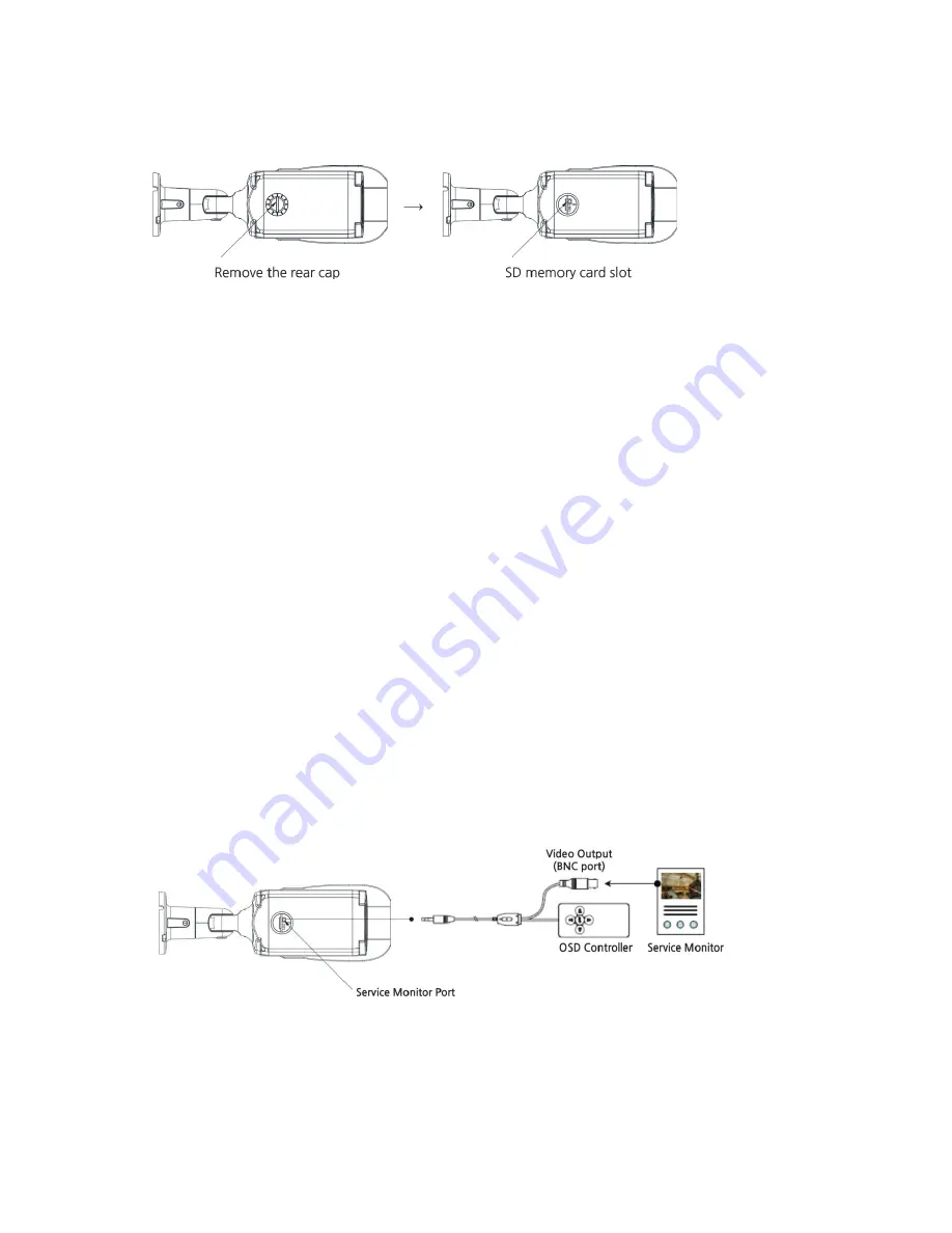
Micro SD memory slot
Remove the rear cap of the camera to insert the SD memory card.
Connecting to the RJ-45
Connect a standard RJ-45 cable to the network port of the network camera. Generally
a cross-over
cable is used for directly connection to PC, while a direct cable is used for connection to a
hub.
You can also use a router featuring PoE (Power over Ethernet) to supply power to the camera.
Connecting Alarms
AI(Alarm In):
You can use external devices to signal the network camera to react on
events.
Mechanical or electrical switches can be wired to the AI (Alarm In) and G (Ground) connectors.
G(Ground):
Connect the ground side of the alarm input and/or alarm output to the G
(Ground)connector.
AO(Alarm Out):
The network camera can activate external devices such as buzzers or lights.
Connect the device to the AO (Alarm Out) and G (Ground) connectors.
Connecting the Power
Connect the power of 12 VDC for the network camera. Connect the po) pole to the ‘+’ position
and the negative (-) pole to the ‘-’ position for the DC power.
–
Be careful not to reverse the polarity when connecting the power cable.
–
A router featuring PoE (Power over Ethernet) can also be used to supply power to the
camera.
–
For the power specifications, refer to the Appendix, Product Specification.
–
If PoE and 12 VDC are both applied, the camera will be supplied with power from PoE.
Connecting Audio
Connect Speaker to Audio line output and external Mic to Audio input line.
Connecting Service Monitor Port
Service monitor output port is located on the board of the camera.
* It does not support the external OSD controller.
Summary of Contents for VK2-108VRDIR35V16e
Page 2: ...2...


