www.vissonic.cn
VISSONIC ELECTRONICS LIMITED
14
7.
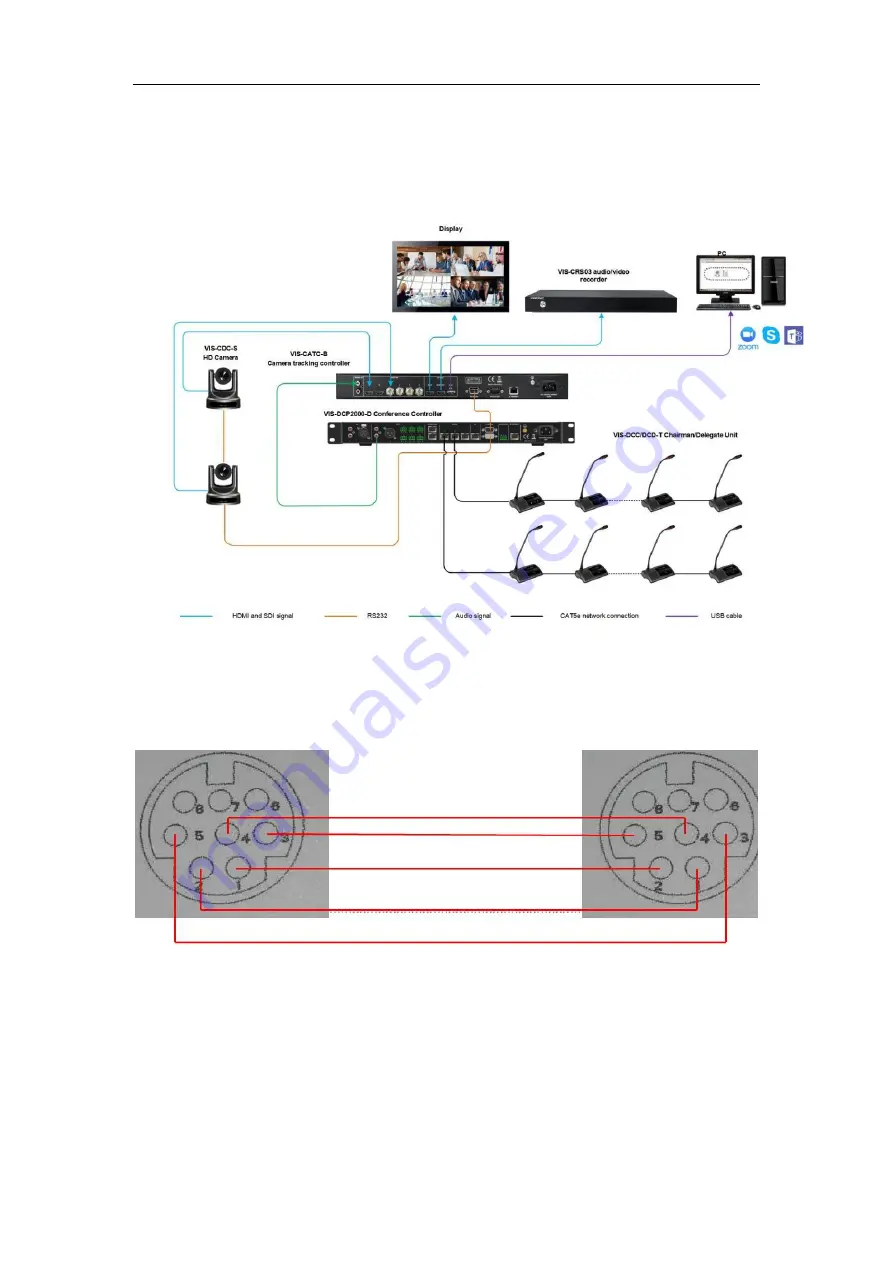
System connection diagram
7.1
Camera RS232 cascade control line connection method
PIN1……DTR; PIN2……DSR; PIN3……TXD; PIN4……GND; PIN5……RXD; PIN6……GND ; PIN7……IROUT; PIN8……NC
Page 1: ...www vissonic com VISSONIC ELECTRONICS LIMITED 1 VIS CATC B Camera Auto tracking controller User Manual V2 1 Version VISSONIC ELECTRONICS LIMITED ...
Page 2: ...gerous voltage without insulation occurring within the equipment may cause people suffer from shock CE certification means that the product has reached the directive safety requirements defined by the European Union Users can be assured about the use of it SGS certification means that the product has reached the quality inspection standards proposed by the world s largest SGS This product passed t...
Page 3: ...shall be connected to the grid power output socket with protective grounding connection Only after cutting down all external power source can install wiring operation begin or it may cause electric shock or equipment damage This product grounds by the grounding wires To avoid electric shocks grounding wires and the earth must be linked together Before the connection of input or output terminal ple...
Page 4: ...www vissonic cn VISSONIC ELECTRONICS LIMITED 4 Version Version Update Date 1 0 Publish 2018 12 28 2 0 Update interfaces and functions 2021 12 07 2 1 Update screen split function 2022 05 07 ...
Page 5: ...nt and rear panel function description 7 4 Installation 8 4 1 19 inch installation cabinet 8 5 Connection 9 5 1 Power supply 9 5 2 RS 232 control interface 9 6 Web Control 11 7 System connection diagram 14 7 1 Camera RS232 cascade control line connection method 14 7 2 Full Digital Network DSP Conference Controller CAMERA Menu Camera Tracking Settings 15 ...
Page 6: ...gital audio input b Video input port 2 channel HDMI HD interface HDMI supports 1080P60Hz downward compatibility supports digital audio input c Video input port 1 channel RCA audio interface analog audio d Video output port 2 channel HDMI HD interface HDMI supports 1080P60Hz downward compatibility supports up to four screen splits output supports audio output e Video output port 1 channel USB inter...
Page 7: ...3 5kg n Power consumption 8W 3 VIS CATC B camera tracking seamless switching controller front and rear panel function description Figure 3 1 VIS CATC B the front and rear panels The front panel of camera tracking includes 1 Power switch turn the power of the camera tracking controller on or off 2 Control button 1 6 button corresponds to 1 6 HDMI and SDI input channels can switch any 1 HDMI or SDI ...
Page 8: ...to connect the full digital network DSP conference controller for video switching control of camera tracking or connect the computer for control 8 Power input port connect the camera tracking controller to the power sequencer or plug in with the power cable to supply power to the camera tracking controller HDMI and SDI input interface supports digital audio input HDMI and USB output interface supp...
Page 9: ...ce Figure 5 2 1 RS232 female It is used to connect the digital network DSP conference main unit for video switching control of camera tracking or connect the computer for control Pin Signal Description Pin Signal Description 1 Null 6 Null 2 TXD Send data 7 Null 3 RXD Receive data 8 Null 4 Null 9 Null Warning The controller power supply needs to be well grounded to avoid causing fatal accidents ...
Page 10: ...nd Serial port default settings Baud rate 9600bps Parity 8 Stop 1 Serial control command table Instruction Function Return Information Remark x V y x input to y output video switching V x y Splice_mode x Multiple image mode selection Splice_mode x x 0 11 Audio_chn x Audio channel selection Audio_chn x FREEZE x Set the screen freeze time to x seconds FREEZE x x Unit second SetFreeze Perform screen ...
Page 11: ...x2 x3 x4 SUBR x1 x2 x3 x4 Set subnet mask SUBR x1 x2 x3 x 4 SHAR x1 x2 x3 x4 x5 x6 Set hardware address hex SHAR x1 x2 x3 x 4 x5 x6 NETDEFAULT Network restore factory settings 6 Web Control Network port default settings IP 192 168 1 189 1 Connect your PC to the Ethernet port of the camera tracking controller via a CAT5 cable 2 Please set your computer to the following IP range ...
Page 12: ...9 and if you can log in to the interface as shown in Figure 6 2 it means that the connection is successful Click Video and Audio to control the screen segmentation and audio switching of the camera tracking controller Screen split as shown below 1 2 3 Figure 6 2 Screen split 1 Signal list the video input signal of the camera controller ...
Page 13: ... Display window After selecting the desired multi image mode you can drag and drop various video signals directly on the display window Audio switching as shown below 1 4 Figure 6 3 Audio switch 4 Audio switching 1 channel analog audio and 6 channel digital audio input can be switched to output arbitrarily ...
Page 14: ...ww vissonic cn VISSONIC ELECTRONICS LIMITED 14 7 System connection diagram 7 1 Camera RS232 cascade control line connection method PIN1 DTR PIN2 DSR PIN3 TXD PIN4 GND PIN5 RXD PIN6 GND PIN7 IROUT PIN8 NC ...
Page 15: ...255 Off 001 to 255 Off 001 to 255 Camera select select the camera to setup there totally support 16 cameras Camera addr set the camera address for the camera selected on submenu Camera select SAMSUNG and PELCO D protocols need to set the address and VISCA protocol is set to off Video channel Bind the camera which set on submenu camera select to the video channel number of video switcher There are ...
Page 16: ...mera Step 8 Repeat the step 2 step 6 to finish the camera 02 More camera are set as the same way Step 9 After setting the last microphone on and off the MIC we can adjust the camera to give a full view of the meeting and press ESC to quit from the menu of Start Set The preset of full view will be active while there are no microphone on Example Here we have to set up two cameras using the VISCA SAM...
Page 17: ...CONTROL is connected with the RS232 port of the camera tracking controller VIS CATC B Step 3 Use the front panel of the conference processor and the camera remote control keyboard or CLEACON software to set the camera tracking preset position and input the camera information according to the following steps ...
Page 18: ...www vissonic cn VISSONIC ELECTRONICS LIMITED 18 ...