


VISLINK
Flydrive 120-150 Antenna
12
3.2
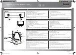
ANTENNA ASSEMBLY – ROOF RACK MOUNT CONFIGURATION
Warning:
The antenna should be fitted with the reflector facing the rear of the vehicle to
reduce wind loads during transit and protect the feedhorn assembly.
All fasteners and fitting that hold the antenna onto the vehicle and hold parts of
the antenna together should be checked before every journey. If any fasteners
are damaged then the vehicle should not be driven with the antenna fitted to
the roof rack. Try to push and pull the antenna out of its locked position. If any
movement is seen then the roof rack fittings should be tightened.
All checks associated with the roof rack should also be carried out.
If you are in any doubt that the antenna and all its parts are not securely held in
place then do not drive the vehicle with the antenna fitted to the roof rack.
The load capacity for the roof rack and vehicle should not be exceeded and
Advent recommends the use of higher load capacity roof rack components. For
example, a set of Thule 755 feet have a rated maximum load capacity of 100kg
compared to 75kg for standard feet. The increased load capacity will improve
the system stiffness and so reduce any RF losses.
Fit the roof rack (not supplied) to the vehicle if not already present. The roof rack bars
and feet and vehicle should be capable of supporting the antenna weight including any
amplifier and/or RF options. If there is an option for a high strength/stiffness rack, then
this should be fitted (for example, Thule supply reinforced load bars and higher load
capacity feet).
As with the flyaway configuration, fit the reflector centre section if the antenna was
stowed in its sub 32kg configuration.
Fit the antenna base front roof rack rails onto the main antenna base. The rear roof rack
rails are permanently fitted to the antenna base.
Slide the roof rack feet onto the rails and fit the end caps. Ensure that the end caps are
pushed fully into the roof bars. Use the end caps with the short extensions on the rear
bars and the end caps with the long extensions on the front bars.
Open up the roof bar feet sufficiently so that they may be slid over the roof rails on the
vehicle.
Lift the antenna base onto the roof rack bars and slide the roof rack feet so that they are
positioned at the correct width to fit the roof rack. Engage the roof rack feet over the roof
rack bars and tighten the roof rack feet and push the end cap fully in.
Partially deploy the antenna as with the flyaway configuration. Fit the lower and upper
feedarm and connect all cables and flex/twist waveguide. Fit the outer reflector
segments.
Note: - Consideration should be given to the vehicle suspension movement during
operation. Ideally jacks should be used to lock the vehicle suspension during operation
and may be necessary for operation at the higher end of the specified operational wind
speeds. If the vehicle does not have its suspension locked off and the wind loads do not
affect the antenna performance, movement due to people entering or leaving the vehicle
can be significant and may result in a temporary reduction in RF performance. Steps
should be taken to reduce the chance of this happening.
If the optional HPA mounting kit is supplied, fit the mounting brackets onto the HPA and
Summary of Contents for AFD120 DBS
Page 2: ...VISLINK Flydrive 120 150 Antenna This page left intentionally blank ...
Page 4: ...VISLINK Flydrive 120 150 Antenna ii This page left intentionally blank ...
Page 6: ...VISLINK Flydrive 120 150 Antenna 2 EMC DECLARATION ...
Page 35: ...VISLINK Flydrive 120 150 Antenna 31 Figure 5 5 a Figure 5 5 b Figure 5 5 c ...
Page 42: ...VISLINK Flydrive 120 150 Antenna 38 FIGURE 8 SATELLITE GEOMETRY ...


![Panorama Antennas L[G]M[X] Series Installation Instructions preview](http://thumbs.mh-extra.com/thumbs/panorama-antennas/l-g-m-x-series/l-g-m-x-series_installation-instructions_3471305-1.webp)


