VisionStat Plus MA-BCKS-5.6 Installation & User Manual Download Page 10

10  

Mobile Awareness 

Installation: Monitor and Wiring Harness 

Before installing the system, it is recommended 
to  temporarily  connect  all  components  and 
perform  a  system  function  check.  If  the  system 
does 

not 

operate 

properly, 

see 

the 

troubleshooting section of this manual. If further 
questions 

arise, 

please 

visit 

www.mobileawareness.com  or  contact  Mobile 
Awareness directly. 
 
The  Monitor  can  be  flush  mounted  in  the  dash 
(with the included mount), with the “U-Bracket” and 
thumb  screws  (see  Figure  11)  or  via  the  Dash 
Mount  Bracket  (see  Figure  12).  Make  sure  the 
mounting  location  does  not  obscure  the  drivers 
viewing area.  
 

NOTE: 

For  other  mounting  options,  please  visit 

www.mobileawareness.com 
 

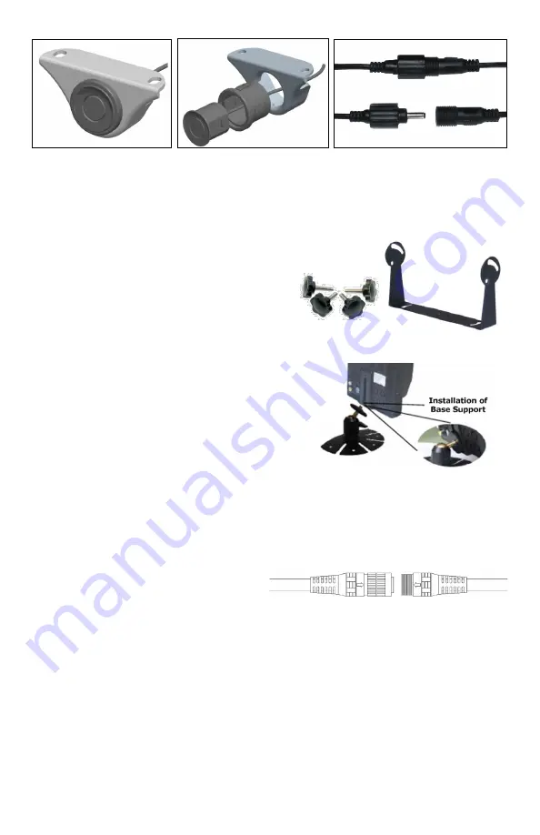
Fig 11: U - Bracket and Thumb 

The VisionStat Plus system includes a 22-pin wiring harness. This wiring harness will 
power the entire system, including the Monitor and up to 4 Cameras. Once the Monitor 
is  mounted,  align  the  Monitor’s  22-pin 
connection  with  the  22-pin  connection  of 
the  wiring  harness.  Each  connector  will 
have  an  arrow  to  assist  with  the 
alignment.  
 
Once engaged, slowly rotate the metal ring to thread the two connectors together. This 
should be done with caution so that the connectors seat and thread together properly. 
You  may  need  to  continue  pressing  the  connectors  together  while  rotating  the  metal 
ring  to  facilitate  the  assembly.  Following  these  steps  will  ensure  the  connection  has 
been  made  correctly.  Failing  to  do  so  may  cause  problems  with  power,  audio  and 
video  connections.  Twisting  the  cable,  or  the  connectors  themselves,  to  tighten  the 
connection  may  result  in  breakage  of  the  pins  and  their  connections,  rendering  the 
wiring harness defective.  
 

Fig 12: Dash Mount Bracket 

Fig 13: 22-pin Wiring Harness 

Fig 8: Sensor in Metal 

Bracket 

Fig 9: Sensor, Rubber 

Sleeve & Metal Bracket 

Fig 10: Waterproof Thread-

ed Sensor Connectors 

Summary of Contents for MA-BCKS-5.6

Page 1: ...odels Installation User Manual Please read this manual thoroughly before operating the device and keep this document for future reference VisionStat Plus Video Monitoring and Obstacle Detection Sensor...

Page 2: ...IN THIS LIMITED WARRANTY Please refer to Mobile Awareness standard Terms and Conditions Customer must notify Mobile Awareness within 10 days of discovering the defective product or part and provide a...

Page 3: ...to the driver while operating the vehicle In any installations where such products are used to display television broadcasts or recorded video playback installation location must adhere to applicable...

Page 4: ...Never puncture scratch or use abrasive cleaning materials on device 7 Do not place cables where they may be pinched or stepped on 8 Leave at least a 2 space between the Monitor and walls cabinets or o...

Page 5: ...also contains a built in micro phone to further aid the driver with audio from behind the vehicle The rugged high resolution image CCD Camera is constructed of a metal allow shell designed to be water...

Page 6: ...ance Detection 0 72 8 20 ft 0 22 2 5 M Detection Tolerance 0 8 inches 0 02M at 25 C Operating Temp ECU and Sensors 30 C to 75 C Monitor and Camera 20 C to 70 C Storage Temp 30 C to 80 C Dimensions ECU...

Page 7: ...te Control Optional Items and Accessories VisionStat Truck Trailer Interconnect System One Camera P N MA BCKS TTC7 Up to Four Cameras P N MA BCKS 4CTTC7 4 pin Extension Cables 5M P N MA EC 405 10M P N...

Page 8: ...full function remote control The VisionStat Plus Monitor is available in two sizes 5 6 and 7 0 Fig 2 7 0 Wired Monitor Fig 1 5 6 Wired Monitor The VisionStat Plus system will combine both the Camera f...

Page 9: ...puts all contained in a waterproof enclosure There are four 4 integrated cables labeled S1 S2 S3 and S4 which will connect to the four 4 each Sensor Units There are two mounting holes for securing the...

Page 10: ...system including the Monitor and up to 4 Cameras Once the Monitor is mounted align the Monitor s 22 pin connection with the 22 pin connection of the wiring harness Each connector will have an arrow t...

Page 11: ...Brown Trigger Wire Trigger Wire for Channel 3 Green Trigger Wire Trigger Wire for Channel 4 Yellow RCA Video Output White RCA Audio Output The trigger wires can be used to achieve hands free operatio...

Page 12: ...pacts Install the Camera in a location where it will be secure Take the necessary measures to reinforce and securely support the Camera if it will be exposed to uncommon amounts of stress and or vibra...

Page 13: ...ver onto the Side Camera Cover Place the included Rubber Insulating Pad in the location where you plan to mount the Camera and use it as a template to mark and drill the 4 each mounting holes Follow b...

Page 14: ...t hold the cover onto the side Camera frame Carefully place the VisionStat logo clip on the lower front area of the side Camera as sembly by snapping the two 2 prongs into the open slots to the right...

Page 15: ...ket properly orientated UP in the hole first Then insert the Sensor again properly orientated UP see Figure 24 Depending on the thickness of the bumper and construction the hole diameter may need to b...

Page 16: ...ing sure to use the Flat Washer 0 375 inch out side diameter in the front of and in back of each unit If the screw is not long enough be sure to use 6 32 Stainless Steel Socket Hex Screws only 1 Begin...

Page 17: ...ne in Figure 28 This angle helps to compensate for weight added to trucks which causes the back end to lower As a result the Sensor may point slightly toward the ground This could cause the Sensor to...

Page 18: ...top and S2 and S3 on the bottom of the vehicle It is recommended that the face of all Sensors should be on the same plane to maximize the accuracy of the system Sensors can also be mounted across the...

Page 19: ...37 Sensor Configuration and Blind Zones A Initial Test With the vehicle in park and your foot on the brake shift the vehicle into reverse The display which remains blank at all other times will turn...

Page 20: ...on the Monitor in order to adjust the level of each setting 3 System The System menu will give you the option of which type of Color System to use turning the blue Back Screen on or off the horizontal...

Page 21: ...d in reverse the system will retest the Sensors indicating if the problem still exists D Minimum Detection Distance The minimum detection and display distance is 8 7 inches 22cm a person or an object...

Page 22: ...terfer ence such as those from ultrasonic or electro magnetic fields The Sensor operates at 40 kHz Noise in or around that frequency may create interfer ence No Picture or Sound Does the Monitor Power...

Page 23: ...e is too low No Color Adjust color settings Upside down or inverted picture Use the remote control horizontal vertical selection switch to set proper orientation This can also be done using the Menu b...

Page 24: ...requires the full atten tion and skill of the driver If a driver is unsure or does not know where crewmembers are or where objects are behind the truck do not back STOP Get out of the cab and physical...

Page 25: ...25 VisionStat Plus Video Monitoring and Obstacle Detection Sensor System Notes...

Page 26: ...26 Mobile Awareness Notes...

Page 27: ...27 VisionStat Plus Video Monitoring and Obstacle Detection Sensor System...

Page 28: ...www mobileawareness com BCKS 2103 INS R1 0...

Reviews: