background image

12


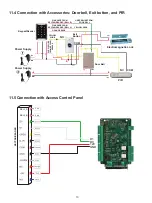
11.2 Connection with Accessories: Doorbell and Exit button

11.3 Connection with Accessories: Doorbell, Exit button, and Wireless 

        Receiver

Power

Supply

Electromagnetic Lock

Exit Button

COM

NO

(COM)

PURPLE WIRE

Keypad/Reader

FROM KEYPAD/READER

(NC)

ORANGE WIRE

PINK WIRE 

(BELL B)

FROM 

KEYPAD/

READER

GREEN WIRE 

FROM DOOR 

BELL

FROM KEYPAD/READER

(OPEN)

YELLOW WIRE

PINK WIRE  FROM  KEYP

AD/READER (BELL

 A)

Door Bell

YELLOW WIRE 

FROM DOOR BELL

FROM KEYPAD/READER

Exit

Button

COM

COM

NO

NO

NC

Power

Supply

Receiver

Power

Supply

Power

Supply

Electromagnetic Lock

Keypad/Reader

ORANGE WIRE FROM 

KEYPAD/READER

PINK WIRE  FROM 

KEYPAD/READER

(BELL B)

PINK WIRE  FROM 

KEYPAD/READER

(BELL A)

YELLOW WIRE

Door Bell

YELLOW WIRE FROM KEYPAD/READER

PURPLE WIRE FROM 

KEYPAD/READER

Summary of Contents for VIS-3000

Page 1: ...Standalone Access Control for Single Door www visionistech com User Manual VIS 3000 VIS 3003 VIS 3000 VIS 3003...

Page 2: ...than 30mA Input Output Wiegand26 Searching Time Less than 0 1s after reading card Backlight Keypad Easy to operate at night Doorbell interface Support external wired doorbell Access ways Card code car...

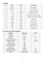
Page 3: ...ontact 9 ALARM Gray Alarm Output 10 NO Blue Relay NO end 11 COM Purple Relay Com end 12 NC Orange Relay NC end 6 Sound and Light Indication Operation LED Color Buzzer Standby Red flash Press key Di Re...

Page 4: ...ad transmission format To set Wiegand format Standalone mode factory default setting Red Flash Stand by Red Flash Red Red Master code Code length 6 8 digits Master code Code length 6 8 digits Red Red...

Page 5: ...se mode Relay Setting Toggle mode To set open door by multi cards To add a series cards users Users can be deleted continuously without exiting programming mode Card number ID number card number ID nu...

Page 6: ...back the up operation pressing means to exit the operation 7 When add a series cards this unit will make the ID number and card number as initial value after adding one user then it will increase the...

Page 7: ...ne anti duress PIN for one device Press 00 new code repeat new master code Note Master Code length 6 8 digits 8 1 Change the master code Set manager add card Press 01 read manager add card 8 2 Set Man...

Page 8: ...ard the PIN is any 4 6 digits but cannot be 1234 Note All users will be deleted 8 8 Delete user 8 9 Set opening door mode 8 10 set door relay time 8 8 1 Read card to delete user 8 9 1 Entry is by card...

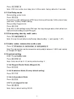
Page 9: ...et Relay mode 8 12 Set opening door by multi cards 8 13 Add a series consecutive cards users 8 14 system setting Note 0 99 is to set the door delay time 0 99 seconds factory default is 5 seconds Press...

Page 10: ...ing Disable keypad backlight Press 43 0 Disable LED light Enable keypad backlight Press 42 1 Automatic mode factory default setting Press 42 2 The keyboard light is off during standby the light is on...

Page 11: ...nuously read Manager Delete card again Relay setting pulse mode Every time a valid card tag read or PIN input the relay will operate for the pre set relay pulse time If the device is disassembled ille...

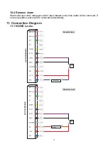
Page 12: ...ger card or input master code then alarm will be removed If no any operation alarm will be removed automatically BELL_B BELL_A 12V P ink P ink DC 12V Door Strike KEYPAD READER Normally Open BELL_B BEL...

Page 13: ...FROM KEYPAD READER GREEN WIRE FROM DOOR BELL FROM KEYPAD READER OPEN YELLOW WIRE PINK WIRE FROM KEYPAD READER BELL A Door Bell YELLOW WIRE FROM DOOR BELL FROM KEYPAD READER Exit Button COM COM NO NO N...

Page 14: ...Panel BELL_B BELL_A 12V P ink P ink D1 D0 12V GND Power Supply Electromagnetic Lock Exit Button Keypad Reader Power Supply COM NO NC PIR COM Door Bell PINK WIRE FROM KEYPAD READER BELL B GREEN WIRE FR...

Page 15: ...ze Quantity Remarks Keypad 1 User manual 1 Self tapping screws 4mm 28 mm 2 Used in fixing Rubber plug 6mm 30 mm 2 Used in fixing Star screw driver 20mm 60mm 1 Special for Keypad a Please do not to rep...

Reviews: