background image

Affixing Hooks and Shelf Brackets

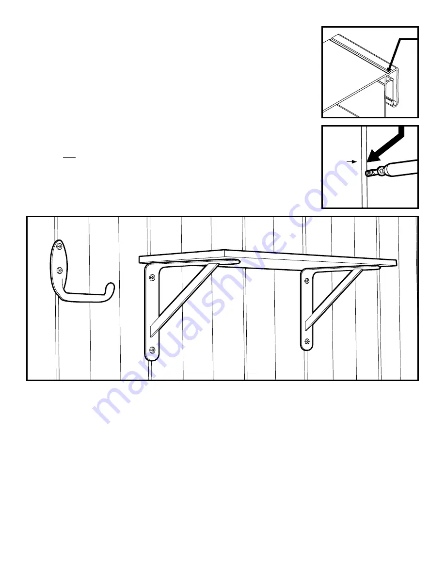
Hooks, shelving and other storage devices can be installed on the walls of your Vision Vinyl 

Shed just as simply as in your garage.

Screws or other threaded fasteners to affix hooks, hangers and shelving, should be inserted 

ONLY in the scored (indented) groove

 located 3/8" to the side of the seam created by the 

joint of two wall panels (See Figures 20A and 20B).

DO NOT INSERT SCREWS DIRECTLY IN THE JOINT BETWEEN TWO WALL PANELS.

It is recommended that fasteners be 

self tapping screws no longer than 1-inch long


and at least 

#10 in size

. (Screws provided with certain hanging devices may be longer or 

inappropriate for this application). Screws may be inserted using a power screw driver, driver 

drill or manual screw driver. Bring screws to a snug fit but do not overtighten. 

DO NOT

 ATTEMPT TO COUNTERSINK SCREWS. DO NOT USE STAR-TYPE OR TOGGLE 

(MOLLY) BOLTS

Follow hanging instructions that accompany the hooks or brackets relative to spacing  

of supports and the number of fasteners to be used. Weight limits identified for the hooks, 

brackets or shelf standards should be strictly observed.

20A

20B

Joint

19

15

Summary of Contents for S-8070-A

Page 1: ...8 x 7 Vinyl Storage Shed PLEASE READ OWNER S MANUAL COMPLETELY BEFORE ASSEMBLING YOUR BUILDING ALL STATED SIZES ARE NOMINAL DIMENSIONS Owner s Manual 8 x 7 2 44m x 2 14m Model S 8070 A Storage Shed...

Page 2: ...re missing please contact the Vision Help Line DO NOT ATTEMPT TO ASSEMBLE THIS PRODUCT IF ANY PARTS ARE MISSING OR DAMAGED Please do not attempt to return this product to the store where you purchased...

Page 3: ...Header RGA 2 RGA 2 RGB 2 RGB 2 Gable End Cap F512G02 F512G02 Door Door NOTE Before assembly of this structure Please take a complete inventory of the parts and components contained in the shed pallet...

Page 4: ...2 8 x 1 Pan Head Screws 150 Hinge Screws 12 8 x 3 4 Pan Head Screws 65 Parts Identification Tools Required Power drill with Phillips 2 or a 2 square bit Carpenter s square Level Rubber mallet Hammer...

Page 5: ...red for your locate climate and soil type Certain building codes may apply as well Request the concrete foundation be made 2 inches larger around all sides than the overall dimensions of the storage s...

Page 6: ...in direct contact with the ground Either support the wood structure on blocks or preferably pour and level a gravel base as a start to your project Using the materials list below you may be able to ha...

Page 7: ...will be match up CHECK 72 1 2 door opening dimension between front Base Tracks NOTE Holes in exterior of Base Tracks are for drainage only DO NOT INSTALL SCREWS IN THESE DRAINAGE HOLES Apply a contin...

Page 8: ...ll section on the flat surface in a similar fashion making sure that the DEEP Channel lock is mated to the SHALLOW Channel lock NOTE If you mistakenly connect two DEEP Channel locks or two SHALLOW Cha...

Page 9: ...post will now have its DEEP Channel lock facing outward to start the left side wall 5 Panel Assembly Left Side Wall Again on a clean flat surface lay out several of the side wall panels there is no di...

Page 10: ...he lintel into the door opening resting it on the door frame Diagram 8A While standing on a ladder fasten the lintel to the door frame on each side of the opening with the 8 x 1 pan head screws provid...

Page 11: ...e the channel locks to avoid striking the that the open end walls of the fascia gable With your assistant position the roof panel assembly Diagram 11B so that the furthest end of the panel assembly re...

Page 12: ...roof You ll know the ridge cap is fully installed when there are no gaps between the ridge cap and the roof panels 12 Roof Fascia Caps Attach the Roof Fascia Caps over the exposed edge of the roof pan...

Page 13: ...Figure 16A use the following instructions to correct To obtain an even vertical gap between the doors i e the doors are touching at the top or the bottom gently push the building back and forth not si...

Page 14: ...easonably snug Do not overtighten 17 Insert and Fasten Screws to the Interior Components Insert 8 x 1 pan head screws at the seams DRAWING in all predrilled holes on the ridge beam in the slope wall c...

Page 15: ...ecommended that fasteners be self tapping screws no longer than 1 inch long and at least 10 in size Screws provided with certain hanging devices may be longer or inappropriate for this application Scr...

Reviews: