


- 7 -
Prior to taking any readings with the 2310B, each FILTER
and GAIN push-button switch should be exercised several
times for best performance and stability.
4.1
SETUP AND AC POWER:
Each 2310B Signal
Conditioning Amplifier has its own power supply and
may be operated as a freestanding unit (see paragraph
4.1e
), or one or more 2310B’s may be inserted into the
Model 2350 Rack Adapter or the Model 2360 Portable
Enclosure.
CAUTION:
Prior to removing or installing the 2310B
Amplifier or the 2331 Digital Readout into a rack
adapter or enclosure, the ac power cord must first be
unplugged. Refer system setup and all servicing to
qualified technicians. If the 2300 System is used in a
manner that is not in accordance with instructions and its
intended use, the protection provided by the equipment
may be impaired.
4.1a
Turn off all 2310B Amplifiers before inserting
them into the rack adapter or cabinet; the red
POWER button should be in the “out” position,
protruding about 1/4 in
(6 mm)
from the panel.
4.1b
Inside of each 2310B, between the rear panel and
transformer, set the AC LINE slide switch to the
nominal ac line voltage to be used (115 or 230V).
Also on the rear panel check that the recessed
PLAYBACK switch is at the NORM (down)
position.
4.1c
Install the 2310B Amplifiers into the rack adapter
or cabinet, securing the thumb-screw at the bottom
of each front panel.
4.1d
Plug the detachable line cord(s) into the appropriate
2350/2360 receptacle(s).
4.1e
To power a freestanding 2310B for only
troubleshooting/servicing by qualified service
personnel, an individual power cord is required.
A non-CE-approved accessory line cord is
available from Vishay Micro-Measurements as part
number 120-001196.
4.1f
The line cord should be plugged into an ac
receptacle which has a good earth ground for the
third pin.
NOTE: If the plug on the power cord must be
replaced with a different type, observe the
following color code when wiring the new plug:
Black or brown: High line voltage
White or blue: Low line voltage (“neutral” or
“common”)
Green or green/yellow: Earth ground
4.2
GAGE INPUT CONNECTIONS
It is suggested that the 2310B be turned on (press the red
POWER button) and allowed to stabilize while
preparing the input connectors. To prevent powering the
input bridge circuits at this time, turn the EXCITATION
rotary switch to 0.7V and the toggle switch to OFF.
4.2a
Each amplifier uses a separate input plug, which is
supplied. Additional plugs are available from
Vishay Micro-Measurements (see
7.4 Component
Replacement
) or from the plug manufacturer or
distributor. Suggested types:
Amphenol/Bendix PT06A-14-15 (SR)
ITT/Cannon KPT06B14-15P
These connectors are designed to MIL-C-26482
and may be available from other manufacturers. As
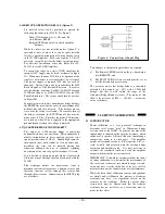
an aid to the technician, the pin arrangement for the
Input plug is shown in Figure 1.
4.2b
The basic input arrangements are shown in Figure
2.
Note that, except when using an external full
bridge, there must be a jumper in the input plug
connecting pins H and J;
this connects the
midpoint of the internal half bridge to the S+
amplifier input. Precision 120
Ω
and 350
Ω
dummy
gages are provided in each Model 2310B. If using
a quarter bridge with resistance
other than
120
Ω
,
350
Ω
, or 1000
Ω
, use circuit A2 in Figure 2. For
1000
Ω
quarter bridges, see Appendix.
4.2c
When using an external full bridge (especially a
precision transducer), it may be desirable to employ
the remote-sense circuitry provided in the 2310B to
maintain constant excitation
at the transducer
regardless of lead resistance. To enable this circuit,
open the right side-cover of the 2310B and raise the
small red SENSE switch to REMOTE (see Figure
4). Connect the sense leads between the transducer
and pins F and G of the INPUT plug as shown in
Figure 2, C2.
4.2d
If it is desired to employ shunt-calibration across
one of the
external
bridge arms, additional wiring
is required to achieve maximum accuracy (see
5.0
Shunt Calibration
for details). However, for half-
or quarter-bridge inputs, shunting the internal
dummy half bridge or dummy gage is normally
recommended; neither of these circuits requires
additional wiring from that shown in Figure 2.
4.0 OPERATING PROCEDURE
Figure 1: Input Plug Pin Arrangement