


- 16 -
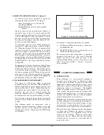
CKT 1: Shunt Internal Half Bridge
Excitation SENSE: LOCAL
Cal Selector Switches:
#1 closed (P+ at INT)
#3 closed (P- at INT)
#5 closed (S+ at INT)
Others open (down)
Ra = 350
Ω
K’ from Equation 11
USE: Quarter and half bridge (full bridge
with reduced accuracy).
ADVANTAGES: Same resistors for any
active gage resistance. No special wiring.
+ and – cal.
DISADVANTAGES: Must correct for
leadwire resistance.
CKT 2: Shunt Dummy Resistor
Excitation SENSE: LOCAL
Cal Selector Switches:
#3 closed (P- at INT)
#9 closed for 120
Ω
gage
Or #10 closed for 350
Ω
gage
(S- at D120 or D350)
Others open (down)
Ra = nominal gage resistance
K’ = K
(Note: If cal Selector #1 is also closed,
can also simulate compression, but for
compression, K’ must be from Eq. 11).
USE: True quarter bridge.
ADVANTAGES: Automatically corrects
for leadwire resistance when using 3-wire
circuit. No special wiring. Accuracy
independent of precise gage resistance.
DISADVANTAGES: Useable only if
internal dummy gages are in use.
Simulates tension only.
CKT 3: Shunt Active Gage
Excitation SENSE: LOCAL
Cal Selector Switches:
#2 closed (P+ to R1)
#8 closed (S- to R4)
Others open (down)
Ra = gage resistance
K’ = K
USE: Quarter, half, full bridge.
ADVANTAGES: Classic theory using
any leadwire method for bridge wiring.
DISADVANTAGES: Two added wires
necessary. Simulates compression only.
CKT 4: Shunt Active Half Bridge
Excitation SENSE: LOCAL
Cal Selector Switches:
#2 closed (P+ to R1)
#4 closed (P- to R2)
#8 closed (S- to R4)
Others open (down)
Ra = gage resistance
K’
≅
K
USE: Half or full bridge.
ADVANTAGES: Classic theory using
any leadwire method (except resistance
between active gages but be negligible).
Sim and -.
DISADVANTAGES: Three added wires
necessary.
Chart 1: Stress Analysis Shunt Calibration Circuits
Many other arrangements are possible, but they must
be used with great care. For example, the obvious
method to shunt an active gage (quarter or half bridge)
would be simply to close the Calibration Selector
Switches for P+, P- and S- to INT, achieving a circuit
functionally similar to Circuit 4. However, the effect
of leadwire resistance is surprisingly high (some
four
times greater than expected
from Equation 11), so the
circuit should never be used; much more accurate
results will be achieved in these cases with Circuit 1
(or especially Circuit 2, if using a true quarter bridge).
5.4
TRANSDUCERS
The term transducer in the context of a bridge
conditioner can include any full bridge composed of
strain gages with a known calibration. It may be
simply four gages properly located on a part to
measure force or torque (frequently a detail part of the
mechanism under study), or it may be a more
elaborate (and accurate) commercial transducer.