V
V
E
E
R
R
T
T
E
E
X
X
™
™
I
I
N
N
T
T
E
E
G
G
R
R
A
A
T
T
I
I
O
O
N
N
P
P
R
R
O
O
C
C
E
E
D
D
U
U
R
R
E
E
This procedure provides instruction to setup and test the communication between a bank
of machines and a Vertex
TM
Jackpot Controller during Production.
REQUIREMENTS
24-00163-00
2 2 O c t 2 0 0 9
F O R I N T E R N A L U S E O N L Y
T h i s d o c u m e n t c o n t a i n s c o n f i d e n t i a l i n f o r m a t i o n t h a t i s p r o p r i e t a r y t o Ar i s t o c r a t . I t m a y n o t b e c o p i e d o r d i s c l o s e d t o u n a u t h o r i z e d p a r t i e s .
© 2 0 0 9 Ar i s t o c r a t T e c h n o l o g i e s Au s t r a l i a P t y L i m i t e d . Al l r i g h t s r e s e r ve d .
1
o f 8
D
D
e
e
s
s
c
c
r
r
i
i
p
p
t
t
i
i
o
o
n
n
P
P
a
a
r
r
t
t
N
N
u
u
m
m
b
b
e
e
r
r
Q
Q
u
u
a
a
n
n
t
t
i
i
t
t
y
y
25ft CAT6 Cable
07-21139
1
24-Port Switch
07-30086
1
Vertex Jackpot Controller
579849
1
Test Cart – Equipped with:
LCD Monitor
USB Keyboard with Built-in USB Hub
USB Mouse
Vertex Power Cord
Vertex CAT5 Cable
N/A 1
PROCEDURE
S
S
T
T
E
E
P
P
1
1
:
:
M
M
o
o
u
u
n
n
t
t
a
a
n
n
d
d
C
C
o
o
n
n
n
n
e
e
c
c
t
t
V
V
e
e
r
r
t
t
e
e
x
x
A
A
.
.
Retrieve the Vertex Jackpot Controller and Switch box from Tek Chek.
B
B
.
.
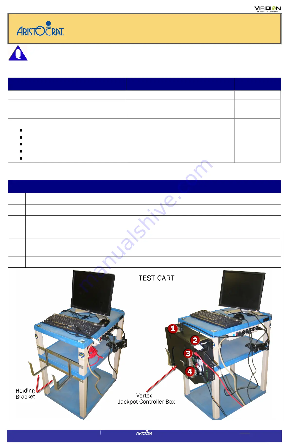
Set the Jackpot Controller inside the holding bracket on the Test Cart as shown.
C
C
.
.
Connect the Power cable into the Vertex box (See No.1 below)
D
D
.
.
Connect the DVI cable (already connected to the LCD) to the Vertex box (See No. 2).
E
E
.
.
Plug one end of the CAT5 Vertex cable (supplied on Test Cart) into the Ethernet Port on the front
of the Vertex box (See No. 3 below).
F
F
.
.
Open the front cover on the Vertex box, and connect the Keyboard USB cable (No. 4).


