


ViPRO Corporation
User
’s Manual
MVR-200-GUI l v1.1 l 2014.07
Mobile DVR MVR-200
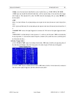
EVENT SETTINGS
12
b.
Name
: enter the text name to identify the source of each sensor, e.g. DOOR OPEN or REVERSE.
c.
OSD
: users can identify the OSD with characters, which is recorded down in the video file when trigger
event happens. When playback the video, the OSD ch
aracter can display after you press “
ENTER
” on
remote control.
d.
SET
:
HIGH - low level effective; the corresponding sensor signal is sent when the sensor input is higher than
3.8 V.
LOW - high level effectively; the corresponding sensor signal is sent when the sensor input is lower than 0
V.
e.
ALARM
: “
OFF
” means the signal triggered is normal event; “ON” means the signal triggered is alarm
event.
f.
LOCK
: “
OFF
” is corresponding to video signed as “U”, which can not be locked; “
ON
” is corresponding
to vide
o signed as “L”, which can be deleted only when unlocked. (The unlock time can be set through the
lock file protection time.)
2)
Sensor Trigger Action
a. FULL SCREEN: “
OFF
” means to shutdown this function; “
ON
” means that the corresponding video of
the channel would display in the direct screen when the sensor signal of that channel is triggered.
b. 3G ACT: “
OFF
” means to shutdown this function; “
ON
” means that the 3G module would be activated
once the sensor signal is triggered, and then upload the screenshot.


