background image

© 2004 Directed Electronics, Inc. Vista, CA

2

23

3

pplluugg--iinn  LLEEDD  aanndd  vvaalleett//pprrooggrraam

m  sswwiittcchh

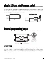
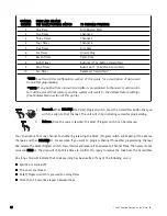
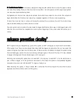
The LED and the Valet/Program switch both plug into the control module. The LED system status indicator plugs

into the white two-pin port, while the Valet

®

/Program switch should be plugged into the blue two-pin port. The

LED and Valet

®

/Program switch each fit into 

9

/

32

-inch holes.

LLEED

D  SSyysstteem

m  SSttaattu

uss  IIn

nd

diiccaatto

orr

V

Vaalleett

®

®

//P

Prro

og

grraam

m  SSw

wiittcch

h

iinntteerrnnaall  pprrooggrraam

mm

miinngg  jjuum

mppeerr  

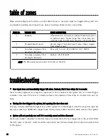
This jumper is used to determine the light flash output. In the (+) position, the on-board relay is enabled and

the unit will output (+)12V on the H1/2 WHITE wire. In the (-) position, the on-board relay is disabled. The H1/2

WHITE wire will supply a (-) 200 mA output suitable for driving factory parking light relays. To access the jumper,

open the control module.

lliigghhtt  ffllaasshh  jjuum

mppeerr

NOTE: JUMPERS ARE
INSIDE THE CASE

DIA-41

Summary of Contents for 320HV

Page 1: ...M Mo od de ell 3 32 20 0H HV V I In ns st ta alllla at tiio on n G Gu uiid de e 2004 Directed Electronics Inc Vista CA N431V 07 04 V VIIP PE ER R...

Page 2: ...e multiplex 16 type H negative multiplex 18 p pl lu ug g i in n L LE ED D a an nd d v va al le et t p pr ro og gr ra am m s sw wi it tc ch h 2 23 3 i in nt te er rn na al l p pr ro og gr ra am mm mi i...

Page 3: ...LI ID DI IT TY Y O OU UT TP PU UT T R RE ED D 1 12 2V V C CO ON NS ST TA AN NT T P PO OW WE ER R I IN NP PU UT T B BR RO OW WN N S SI IR RE EN N O OU UT TP PU UT T Y YE EL LL LO OW W I IG GN NI IT TI...

Page 4: ...Internal Programming Jumper section of this guide P P N N 8 86 61 17 7 or a standard automotive SPDT relay must be used on the H1 2 light flash output harness wire This wire provides a 200 mA output w...

Page 5: ...This wire can also be used with Directed Electronic s 506T Glass Breakage Sensor as well as other Directed Electronic s single stage sensors The H1 6 BLUE multiplex trigger wire can be used to shunt s...

Page 6: ...on source This input must show 12V with the key in run position and during cranking Make sure that this wire cannot be shorted to the chassis at any point This wire will report Zone 5 Connect this to...

Page 7: ...er than 1 5 seconds the red white wire will supply an output as long as the transmission continues This is often used to operate a trunk hatch release or other relay driven function I IM MP PO OR RT T...

Page 8: ...n the driver s door or on the center console Once you have determined which type of factory door lock circuit you are working with and the color codes of the switch wires to be used you can usually si...

Page 9: ...cuum systems The vehicle must have a vacuum actuator in each door Make sure that locking the doors from the driver s or passenger side using the key activates all the actuators in the vehicle This req...

Page 10: ...1 10 0 2004 Directed Electronics Inc Vista CA t ty yp pe e A A p po os si it ti iv ve e t tr ri ig gg ge er re ed d r re el la ay y d dr ri iv ve en n s sy ys st te em m...

Page 11: ...pe B The switch will have three wires on it and one wire will test ground all the time One wire will pulse when the switch locks the doors and the other wire will pulse when the switch unlocks the doo...

Page 12: ...1 12 2 2004 Directed Electronics Inc Vista CA t ty yp pe e C C r re ev ve er rs si in ng g p po ol la ar ri it ty y s sy ys st te em m...

Page 13: ...door This requires mount ing the door lock actuator inside the door Other vehicles may only require one actuator installed in the driver s door if all door locks are operated when the driver s lock is...

Page 14: ...vated vacuum pump The control wire will show 12V when doors are unlocked and ground when locked N NO OT TE E The system must be programmed for 3 5 second door lock pulses and the violet jumper between...

Page 15: ...hese are reversed It is found in the late model Nissan Sentras some Nissan 240SX Nissan 300ZX 1992 and later It is also found in some Mazda MPV s N NO OT TE E The violet jumper between the 87 lock ter...

Page 16: ...tch key cylinder must be isolated from the factory door lock system For testing use a calibrated digital multimeter that is set to ohms I IM MP PO OR RT TA AN NT T To ensure an accurate resistance rea...

Page 17: ...2004 Directed Electronics Inc Vista CA 1 17 7...

Page 18: ...the resistor values the door lock switch key cylinder must be isolated from the factory door lock system For testing use a calibrated digital multimeter that is set to ohms I IM MP PO OR RT TA AN NT...

Page 19: ...lock output is used to unlock the passenger doors N NO OT TE E The second unlock output feature is not available if the double pulse unlock feature is turned on I IM MP PO OR RT TA AN NT T The H2 A wi...

Page 20: ...2 20 0 2004 Directed Electronics Inc Vista CA D Dr ri iv ve er r s s D Do oo or r U Un nl lo oc ck k O On nl ly y T Ty yp pe e A A...

Page 21: ...a single pulse when armed and two pulses when disarmed This wire also provides pulsed output when the security system is in the triggered sequence or in panic mode In most vehicle s with horn circuits...

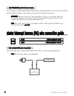
Page 22: ...he addition of the relay accessory package p p n n 8 86 61 17 7 s st ta ar rt te er riin nt te er rr ru up pt th ha ar rn ne es ss s H H4 4 w wiir re ec co on nn ne ec ct tiio on ng gu uiid de e _____...

Page 23: ...y ys st te em m S St ta at tu us s I In nd di ic ca at to or r V Va al le et t P Pr ro og gr ra am m S Sw wi it tc ch h iin nt te er rn na all p pr ro og gr ra am mm miin ng g jju um mp pe er r This j...

Page 24: ...om N NO OT TE E When adjusting the sensor it must be mounted in the same location where it will be after the installation is completed Adjusting the sensor and then relocating the module requires read...

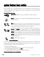
Page 25: ...for programming There is a basic sequence to remember whenever programming this unit Door Key Choose Transmit and Release 1 O Op pe en n a a d do oo or r The GREEN wire H1 5 or the VIOLET H1 7 must be...

Page 26: ...Learning has been exited if any of the following occurs Ignition is turned off The doors are closed Valet Program switch is pressed too many times More than 15 seconds elapses between steps C CH HA AN...

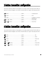
Page 27: ...operates Panic Button operates Trunk Silent Arm Disarm Channel Two Buttons operates Channel Three Buttons operates Channel Four 4 4 b bu ut tt to on n t tr ra an ns sm miit tt te er r c co on nf fiig...

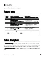
Page 28: ...the Valet Program switch you can select the desired features setting using the remote transmitter Pressing the lock icon transmitter button while H HO OL LD DI IN NG G down the Valet Program switch w...

Page 29: ...TT TI IN NG GS S N NU UM MB BE ER R P PR RE ES SS S L LO OC CK K I IC CO ON N T TR RA AN NS SM MI IT TT TE ER R B BU UT TT TO ON N P PR RE ES SS S U UN NL LO OC CK K I IC CO ON N T TR RA AN NS SM MI...

Page 30: ...erface with double pulse vehicles without any extra parts N NO OT TE E The second unlock output feature H3 1 BLUE wire is not available if the double pulse unlock feature is turned on 7 7 S ST TE EA A...

Page 31: ...void any false triggering of the system while the window are in motion n nu uiis sa an nc ce e p pr re ev ve en nt tiio on n c ciir rc cu uiit tr ry y NPC requires that you change the way you test the...

Page 32: ...of door switch system This often happens when the wrong door input has been used See H1 5 GREEN Door Trigger Input Primary Harness Wire Connection Guide section of this guide S Sy ys st te em m w wi...

Page 33: ...w wi it tc ch h d do oe es s n no ot t w wo or rk k Is it plugged into the correct socket See Plug In LED and Valet Program Switch section of this guide T Th he e L LE ED D s sy ys st te em m s st ta...

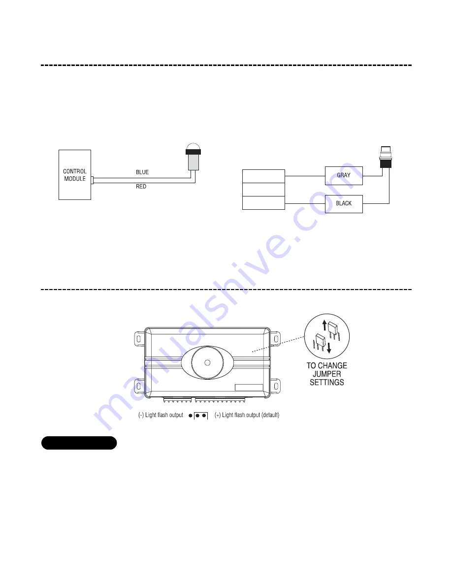
Page 34: ...put Zone 3 Black Chassis Ground Brown Siren output 1A Red Constant Power Red White 200 mA Channel 2 Auxiliary Output Chassis Ground Optional Accessories Domelight Optional Negative Door Pin Switch Neg...

Reviews: