Instructions for use and assembly
2014
Page 8/11
Manufacturer: VIPAMAT FRANCE EN 12-01 Instructions for use and assembly
– V1 - 26/11/2014
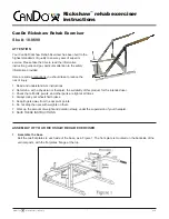
ASSEMBLING THE HARNESS
ASSEMBLING THE BRAKES
Beforehand, check that the tyres pressure is equal to 1,5 bar.
1. Unfasten 2 buckles on the front straps under the seat.
2. Position the lower part of the brake block under the tube in contact with the
camcleat at the front.
3. Position the upper part of the brake block on the frame tube in contact and at the
front of the camcleat, then tighten the upper part of the brake block by tightening the 2
screws alternately.
Caution: the tightness between the upper part and the block must be practically
the same on both sides. Ensure that the stem is horizontal in relation to the tyre
before finishing the tightening.
4. Position the brakes camcleats and loosely screw in the tightening screws to be able
to adjust the camcleats.
5. Lock the brake by jamming the handle on the camcleat (the stainless steel stem is
then in contact with the tyre).
6. Position the camcleat by exaggerating the locking of the brake on the wheel and
tighten the camcleat screws.
7. Verification:
- the brakes blocks mut be stable on the frame tubes (no sliding or rotating).
- the locking brakes must block the tyres by pressing them for an efficient braking.
NB: the serial number of the brakes is engraved on each stainless steel stems of the
brakes.
Adjusting the harness: pull on the buckles at the ends of the harness straps to tighten them. Quick removal:
unfasten the 4 buckles.
The push bar must already be assembled.
Position the harness
1. Place the upper harness straps in the handlebar clasps and fasten them (Figure 9).
2. Slide the lower harness strap through the loops (for each side).
3. Place the lower straps outside the flanges, between the seat and the frame tube,
then pull the strap up after passed it beneath the tube.
4. Slide the strap back through the loop and tighten. (Figure 10)
5. Verifications:
- the positioning direction of the harness (check the figures 9 and 10).
- check the locking straps by stretching on each strap, the assembly must be stable.
9
10