


15
1. Install each unit at their respective location and connect each unit to their Cat5e network cable.
2. Connect each Cat5e network cable to the network switch.
3. Power on the network Switch if not already on.
4. Power on the Master Indoor Monitor.
5. On the Master Indoor Monitor go to SETTINGS > PROJECT SETTINGS > then enter password
002236
6.
Choose NET INFO and change the IP address of this Indoor Monitor from
10.22.5.180
to one that is
in the same network range as your own computer network, in this example we will be using
10.1.1.180
and
press ok to save
.
(see “How to change the Indoor Monitor IP Address”).
7. Choose PROJECT INFO and set the Room number (it must be at least 3 digits, such as
102
) and
press ok to save.
8. Power on the Extension Indoor Monitor.
9.
On the Extension Indoor Monitor go to SETTINGS > PROJECT SETTINGS > then enter the
password
002236
10.
Choose NET INFO and change the IP address of this Indoor Monitor from
10.22.5.180
to another
one that is in the same network range as your own computer network, in this example we will be
using
10.1.1.179
and
press ok to save
. (see “How to change the Indoor Monitor IP Address”).
11. Choose PROJECT INFO and set mode to Extension. You can now set the Room number to the
same as the Master but add “ -1 “ to show that it is the first extension (such as
102-1
). You will have
to enter the IP address of the Master Indoor Monitor
10.1.1.180
and press ok to save.
(see “How to set up an Indoor Monitor as an Extension Monitor”).
12. ----- Repeat Steps 8
–11 for any additional Extension Monitors -----
13. Now that all Indoor Monitors are set up, Power on the first Door Station.
14. Using a PC, find and change the Door Station IP Address from
10.22.5.189
to to another one that is
in the same network range as your own computer network, in this example we will be using
10.1.1.190
and
press ok to save
.
(see “How to change the Door Station IP Address”).
15. Open Internet Explorer and type http://10.1.1.190 in the IE address bar.
16. Log in with the Default factory name of
admin
and password is also
admin
.
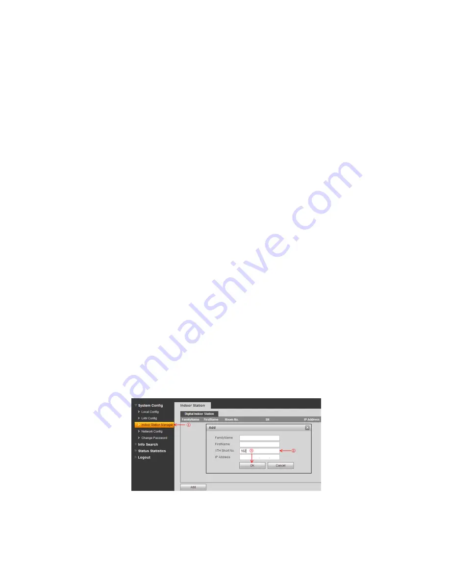
17. Go to SYSTEM CONFIG > INDOOR STATION MANAGER. Delete any default room numbers such
as 9901 then click on “Add” to add a new Room No. Leave the name and IP Address blank and
simpl
y enter the “VTH Short No” which will be the Room No. of your Master Indoor Monitor (such as
102
). Then click Ok to save.
18. Go to SYSTEM CONFIG > LAN CONFIG. Tick the Checkbox to enable
“Group Call”, then click Ok to
save.
Summary of Contents for INTIPRKIT
Page 2: ...2...


