background image

SP-2000/X-Y

Installation

3-4

User Manual

Removing The SP-2000/X-Y From Its Crate

CAUTION: Do not try to push the pedestal off the base of 
the crate and down the ramp. You may cause serious electri-
cal and/or mechanical damage.

CAUTION: At least two people are needed to remove the 
pedestal from the crate.

As shipped from the factory, the on board batteries of the SP-2000/X-Y are fully 
charged. Therefore, unless the dolly is left crated for an extremely long time, it 
can be driven off the skid under battery power using the ramp supplied. If you 
cannot drive the dolly under its own battery power, the alternate procedure 
described below will require the temporary use of the AC power supply and 
power/data cable.

Uncrating The Pedestal

1.

The shipping crate is re-usable and should be saved for repacking the ped-
estal or should be shipped back to Vinten. Make sure that you retain the 
sides, top, ramp, interior brace and the four straps.
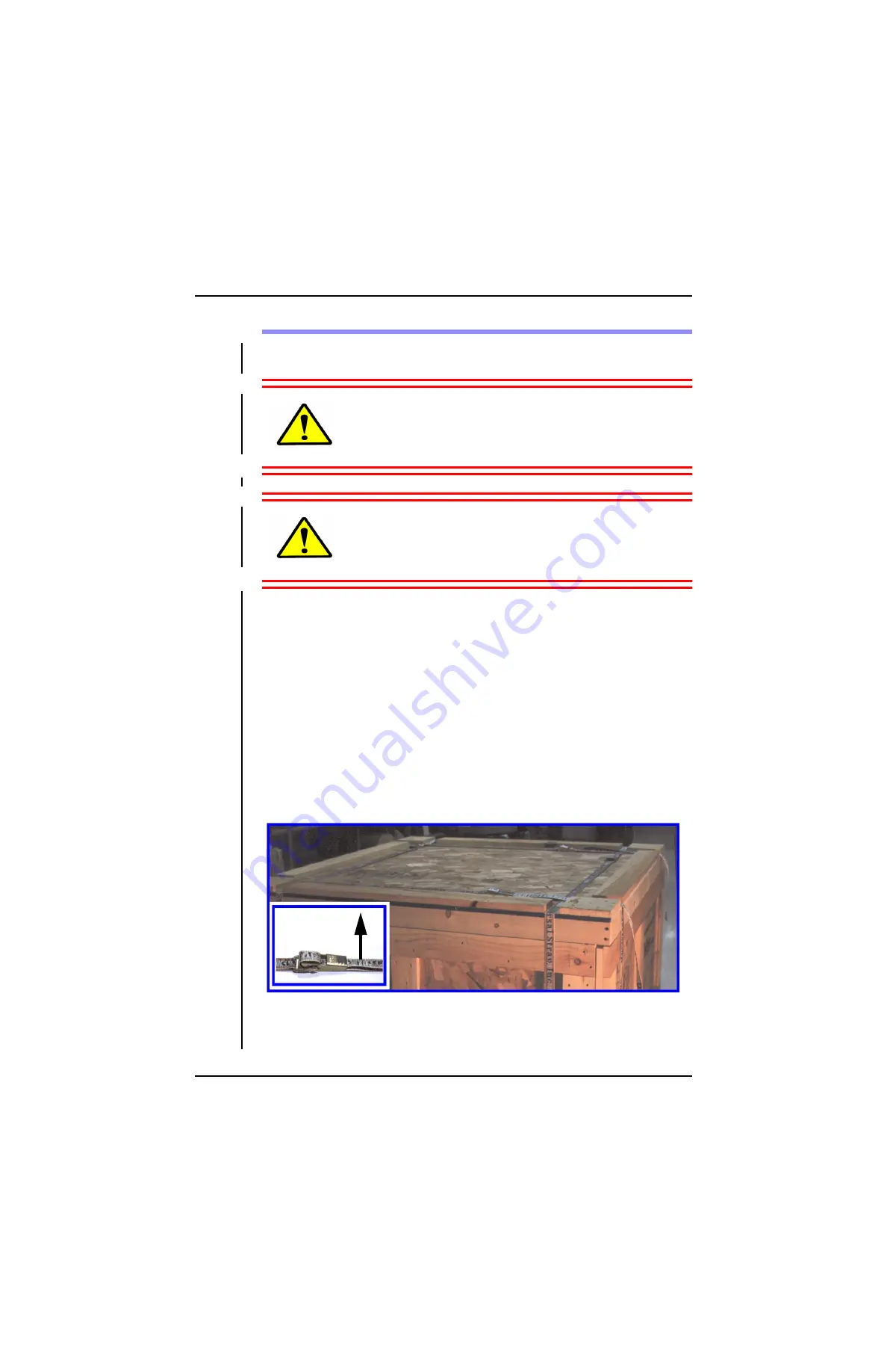
2.

Release the four straps that hold the crate together by pulling up on the 
latch on each buckle. Remove the straps.

3.

Using two or more people, lift the top of the crate and set it aside.

Pull Up

To Release

Summary of Contents for AutoCam SP-2000/X-Y

Page 1: ...i SP 2000 X Y AutoCam Pedestal Operation Installation And Maintenance pn AB 300101 for sn 80xxxx0020 021601 ...

Page 2: ...you to hazardous situations The labels and their meaning are described below DANGER with a red background indicates an imminently hazardous situation which if not avoided will result in death or serious injury WARNING with an orange background indicates a poten tially hazardous situation which if not avoided could result in death or serious injury CAUTION with a yellow background indicates a poten...

Page 3: ...er consumption of the pedestal head and rack mount power supply combined is 1000W maximum Mass Weight 525 lb 239 kg Maximum Load 320 lb 145 kg Maximum Pressure 150 bar 2200 psi Input Voltage 36 VDC nominal Input Power 4 Amps nominal 12 Amps peak Date Of Manufacture 2001 ...

Page 4: ...nc at 709 Executive Blvd Valley Cottage NY 10989 USA Phone 1 888 4 VINTEN 1 888 484 6836 Toll free in the U S A 1 845 268 0100 Fax 1 845 268 0113 Or if you are based outside of North South or Central America contact Vinten Broadcast Limited at Western Way Bury St Edmunds Suffolk IP33 3TB ENGLAND Phone 44 0 284 752121 Fax 44 0 284 750560 ...

Page 5: ...rranty The warranty is in effect only when equipment is operated adjusted and maintained in the manner described in the appropriate Operation Installation and Service man ual Modifications service by non authorized service personnel failure to provide proper maintenance and abuse and misuse of the equipment will void the warranty Repairs not covered by this warranty will be billed for parts labor ...

Page 6: ...e installation operation and maintenance of the AutoCam SP 2000 X Y robotic pedestal See Chapter 1 for a detailed description of the contents of this manual Product Serial Numbers Vinten AutoCam products are marked with unique serial numbers that include a 2 digit product identifier a 4 digit serial number and a 2 character revision code The format is AABBBBXXCD where This manual is applicable to ...

Page 7: ...sibility 1 5 Safe Working Environment 1 5 Safe Operating Zone And Pedestal Footprint 1 6 Pedestal Active Lights 1 6 Warning Signs 1 7 Pedestals And Heads Can Start Unexpectedly 1 7 Collision Bumper And Bumper Override 1 8 Bumper Override 1 8 Pinch Points 1 9 Sharp Edges 1 9 Manual Outline 1 10 The SP 2000 X Y Servo Pedestal 1 12 AutoCam Philosophy 1 14 Seamless Integration Into The Studio 1 14 Lik...

Page 8: ...estals 3 3 Removing The SP 2000 X Y From Its Crate 3 4 Uncrating The Pedestal 3 4 Unloading The Pedestal 3 6 AC Powered Unloading 3 8 Mounting The Pan Tilt Head Payload 3 10 MCB Controller Mounting 3 11 Pressurizing And Balancing The Pedestal 3 12 Pressurizing The Pedestal 3 12 Balancing The Pedestal 3 14 Finishing Up 3 15 Discharging The Pedestal 3 15 Calibrating The Collision Bumpers 3 16 Electr...

Page 9: ...r 4 11 Replacing The Covers 4 12 Cleaning The Target Sensors 4 14 Cleaning The Slip Rings 4 16 Examining The Wheels 4 18 Cylinder Replacement 4 20 Electronics Repair 4 22 Service Philosophy 4 22 Safety 4 22 Calibration 4 24 Collision Bumpers 4 24 Target Sensor Calibration 4 26 Theory Of Operation 4 30 System 4 30 Power Bus 4 30 Data Bus 4 30 Battery Pack and Power Management 4 31 Battery Bypass 4 ...

Page 10: ...Table Of Contents x This page left blank intentionally ...

Page 11: ...User Manual 1 1 1 Safety Introduction ...

Page 12: ...el are aware of the location and operation of these pedestal E STOP switches and the main pedestal power down switch before operating the equipment Press down firmly on any one of the E STOP switches to immediately disable the pedestal and head The Off Switch can also be used but only if the operator can press it quicker that than one of the E STOP switches After clearing the cause for the emergen...

Page 13: ...Make sure that all personnel are aware of the location and operation of these E STOP switches before operating the equipment Press down firmly on the E STOP switch to imme diately disable the associated pedestal and head After clearing the cause for the emergency stop pull up the appropriate E STOP switch The pedestal and head can now be powered up and targeted see Chap ter 2 for operating procedu...

Page 14: ...G NEVER work directly under the camera if the column is raised In the unlikely event that the gas pressure supporting the column is lost the head and payload may drop quickly CAUTION NEVER stand under the payload when you power up the pedestal or switching from Local to Remote on the MCB Controller The column may change height quickly CAUTION NEVER attach cables to the head or camera which could p...

Page 15: ...In normal operation the remote controlled pedestals heads and pay loads in an Autocam system can move suddenly and without warning Since audible warnings are out of the question in normal television applications it is recommended that only trained personnel be allowed to work in the active areas where the remote controlled pedestals heads and payloads are located As part of the training personnel ...

Page 16: ...st take into account the overhang of the teleprompter and or manual control bars as the head pans around If your operating practices require personnel to work less than 3 feet 1m out side the pedestal footprint you must make sure that they are trained and are aware of the hazards of working in a robot environment including the specific hazards listed below The forces are sufficient to cause person...

Page 17: ... that they can move at any time They must be trained on how far the pedestals heads and payloads can move the speeds involved and the need to stay back an appropriate distance Most adjustments to the camera and head such as balancing and camera calibra tion should be made with the system de energized However if adjustments are absolutely necessary while the pedestal and or head is powered they sho...

Page 18: ...pedestal that tripped its bumper A B appears in the column of the pedestal that has tripped its bumper circuit Touch anywhere on the screen to clear the error message and continue operation 3 As soon as is practical check the work area to clear the obstacle that caused the collision and use LOCATE mode see Controller User Manual to back the pedestal away Be aware that the other pedestals in the st...

Page 19: ...he collision bumper system and circuit calibration electro optical bumper type only see Chapter 4 to determine the cause of the failure and take corrective action Pinch Points Particular care should be exercised around possible points where you could get pinched such as the tilt cradle Here the forces can be somewhat greater due to the short lever arm Sharp Edges If the lens teleprompter or other ...

Page 20: ...w of the SP 2000 X Y pedestal and the AutoCam system Chapter 2 Step by step instructions for operating the SP 2000 X Y pedestal Chapter 3 Step by step instructions for unpacking and installing the SP 2000 X Y pedestal Chapter 4 Technical information including routine maintenance circuit descriptions calibra tion schematics and parts lists ...

Page 21: ...SP 2000 X Y Safety Introduction User Manual 1 11 This page left blank intentionally ...

Page 22: ...ervos with a proprietary guid ance and position sensing system which produces a very high degree of accu racy Since the system does not use a closed loop reference the SP 2000 X Y avoids the need for constant visibility of the reference target during use Once the target coordinates have been loaded into the system the pedestal will operate with unparalleled accuracy for extended periods without ne...

Page 23: ... 2000 X Y also includes safety bumpers to stop the pedestal on contact with an object Communication with the controller is by RS422 data via the power supply up to a maximum distance of 5000 feet 1 500 m A slim power data cable connects the pedestal to the rack mounted power supply up to a maximum distance of approximately 180 feet 55 m The SP 2000 X Y incorporates an on board battery for backup i...

Page 24: ...igher reliability Seamless Integration Into The Studio Successful camera automation should be as transparent as possible to the studio staff and particularly to the director He or she should expect the same commu nications with the camera console operator as with multiple camera operators in a traditional studio As before a named shot from the run down list is relayed over the headsets But the ope...

Page 25: ... on the screen is intelligently limited and dynami cally updated only the touch keys that have meaning in a given situation are shown Going one step beyond remote camera control the console adds the capability to memorize essentially any camera event from a simple shot to a dolly bumper or group move The operator now manages by exception directing AutoCam to frame the shots and then trimming them ...

Page 26: ...roller is by RS 422 data Refer to the User Manuals for your specific heads and controller for more infor mation ACP 8000P System In systems with one or more up to eight servo pedestals the ACP 8000P con troller is used as shown below The distance between the controller and rack mounted power supply for the data connection can be up to a maximum of 5000 ft 1500 m The power data con nection from the...

Page 27: ...ion The diagram below illustrates the interconnection of a typical AutoCam sys tem In this example two ACP controllers are installed to provide backup and or workload sharing The 2x1 Data Selector routes the selected data lines to the power supplies and optional CCU interface ...

Page 28: ...SP 2000 X Y Safety Introduction 1 18 User Manual This page left blank intentionally ...

Page 29: ...User Manual 2 1 2 Operation ...

Page 30: ...ter covers operation of the pedestal and is limited to the switches con trols and other features on the pedestal itself Operating procedures for control ling the pedestal remotely are described in the User Manual for the specific controller in your installation ...

Page 31: ... to define the orientation of the pedestal by the points of the compass North South East and West As shown in the picture above the main control panel is on the South side of the pedestal the front wheel of the pedestal is on the North side and the other two wheels are on the East and West sides South West East North ...

Page 32: ... automatically it must be powered up manually 1 Before you power up a pedestal first make sure that the head is turned off the MCB controller is in Remote and the area around the pedestal is clear Warning At power up the column and payload will drop to a low level for a few seconds Make sure that nobody will be hit by any part of the payload Standby Charge Run Stop ...

Page 33: ... the direction indicators on the wheels rotate one by one as they initialize Do not attempt to drive the pedestal until initialization is complete 5 Once the pedestal is powered up and initialized turn on the head Powering Down Always power down the head before the pedestal The pedestal can be powered down to Standby Charge mode or turned off com pletely in Stop mode Or in an emergency use any one...

Page 34: ...ediately by press ing down on any one of the three Emergency STOP Switches on the base of the pedestal or one of the E STOP switches at the operator console An E STOP switch for each pedestal of the type shown below is installed at each operator location and optionally at other locations Emergency STOP Switches 1 Hidden ...

Page 35: ... the cause for the emergency stop release the E STOP switch that was activated On the pedestal twist the E STOP switch clockwise to release it At the operator consloe just pull up on the E STOP switch Power up the pedes tal and head as described earlier ...

Page 36: ...wheel is oriented The red marker shows the forward direction of the wheel In Drive mode all three wheels are parallel to each other This allows the pedes tal to crab in any desired direction In Rotate mode the three wheels are tangen tial to the pedestal circumference allowing it to rotate in place Direction Indicators Hidden ...

Page 37: ...pedestal a pair of green lights will flash to indicate that the pedestal is in motion or may move at any time without additional warning These lights are activated by Locate mode at the controller and do not operate if the pedestal is being controlled locally by the MCB con troller Pedestal Active Lights ...

Page 38: ... With the Rotate switch to the right push the joystick up down left right or any angle in between to drive the pedestal in the desired direction Regardless of the pan angle of the head up down on the joystick drives the pedestal in the North and South direction Right left on the joystick drives the pedestal East and West Rotate With the Rotate switch to the left push the joystick left right to rot...

Page 39: ...operation of the AutoCam system However targeting is initiated at the controller and cannot be performed at the pedestal itself Installing the targets measuring their positions and the targeting procedure are described in Chapter 3 of the User Manual for your controller for example the ACP 8000P ...

Page 40: ...SP 2000 X Y Operation 2 12 User Manual This page left blank intentionally ...

Page 41: ...User Manual 3 1 3 Installation ...

Page 42: ...nt studio or a new facility Refer to the User Manuals for your pan tilt heads and controller for additional information For proper performance of the equipment and to prevent per sonal injury it is critical that the procedures in this manual are followed exactly Tools You Will Need You will need the following tools during the unpacking and installation 2 medium size crescent wrenches 3 16 hex key ...

Page 43: ...ers floors Customers should specify floor covering that is consistent with their anticipated frequency of operation under these load conditions Although Vinten Inc does not make specific floor recommendations customers have reported excellent results with self leveling epoxy over leveled concrete Other issues that you should consider while specifying floor materials are Wear characteristics and ab...

Page 44: ... be driven off the skid under battery power using the ramp supplied If you cannot drive the dolly under its own battery power the alternate procedure described below will require the temporary use of the AC power supply and power data cable Uncrating The Pedestal 1 The shipping crate is re usable and should be saved for repacking the ped estal or should be shipped back to Vinten Make sure that you...

Page 45: ...he crate Unfold the ramp onto the floor 5 Remove the four sides of the crate and set them aside 6 Using two or more people lift the brace frame up and off the pedestal and set it aside 7 Remove and set aside any other items for example the head mounting screws MCB joystick controller targets etc that were packed inside the pedestal crate Ramp Attached To Base Of Crate 3 Side Panels Removed ...

Page 46: ...er plug on the Power Data In connector on the control panel as shown below Without this jumper plug the E STOP logic will prevent battery powered operation 3 The cable skirts around the pedestal base 4 in total must be raised fully before you drive the pedestal off the base of the crate and down the ramp For each skirt loosen the thumbscrews raise the skirt and tighten the thumbscrews E STOP Bypas...

Page 47: ...on on the pedestal until the light comes on and stays on If the batteries are discharged typically below 24V on the control panel voltmeter and the pedestal will not turn on refer to AC Powered Unloading below 6 Press the Run green button on the pedestal and the light will come on and the pedestal circuits will initialize Wait about 30 seconds until all three wheels have initialized the North whee...

Page 48: ... the ramp and onto the studio floor Note Even with the cable skirts raised they may hang up on the top and bottom of the ramp If this happens have an assistant pull up slightly on the pedes tal so that the skirt will clear AC Powered Unloading 1 Connect the Power Data Cable from the power supply Power Data Out connector to the Power Data In connector on the pedestal If the power sup ply is not yet...

Page 49: ...ave the pedestal in Standby Charge mode overnight to charge the batteries Then you will be able to drive the pedestal to its final location using battery power Or if the pedestal is already in its final location you can continue with mount ing the head pressurizing the pedestal and the electrical installation Remove the E STOP jumper plug from the power supply ...

Page 50: ... to help the servo by pushing down on the column 2 Switch the MCB controller to Remote 3 Press the Stop button on the pedestal control panel to power it down 4 Position the screws in the holes in the mounting plate at the top of the col umn 5 Refer to the User Manual for the Pan Tilt Head for specific instructions on mounting the head and payload CAUTION After mounting the head and payload NEVER t...

Page 51: ...t washers provided Tighten the screws with a 3 16 hex key 2 Insert the right angle mounting bar into the bracket and tighten the clamp screws with a 3 16 hex key The final positioning of the bar left right and up down will depend on the camera position and can be adjusted later 3 Mount the MCB controller on the bar and tighten the clamp 4 Plug the MCB controller cable into the Local Control Data c...

Page 52: ... OR NEAR THE PEDESTAL MUST BE TRAINED AWARE OF THE CORRECT PROCEDURES AND AWARE OF THE HAZARDS INVOLVED DANGER THE MAXIMUM CYLINDER PRESSURE IS 1 250 PSI 86 BAR USE ONLY THE VINTEN SUPPLIED MANIFOLD FOR ADJUSTING PRESSURE Pressurizing The Pedestal 1 Make sure that the column locking pins are NOT installed this will allow the column to rise as the pressure is increased Fill Valve 1 of 3 4 Extension...

Page 53: ...e switch while the pedestal is being pressurized until the pedes tal is powered up in step 11 In newer pedestals a set of contacts on the Standy Charge switch perform the function of the Fill Switch 9 Start increasing the pressure setting on the regulator turn CW At approx imately 900 psi 63 bar you will hear a hissing sound indicating that the three holding chambers are being filled Keep the regu...

Page 54: ... the column up and down slowly around its mid point and watch the balance meter on the rear panel of the pedestal 3 If the column is balanced the meter deflection will be equal in both direc tions If the deflection is greater when the column is raised the pressure is too low and gas should be added use step 4 If the deflection is greater when the column is lowered the pressure is too high and gas ...

Page 55: ...inimum height and power down the pedestal 2 Follow steps 1 4 of Pressurizing The Pedestal earlier in this chapter 3 Close the regulator completely close the purge valve on the manifold and open the three T valves turn CW at the ends of the fill hoses 4 Slowly open the purge valve and allow the gas to escape 5 When the pressure reading on the manifold gauge is below 30 psi 2 bar close the purge val...

Page 56: ...ype of bumper you have Before the SP 2000 X Y is put into service it is essential for safety reasons that the collision bumper detection circuits are calibrated Each cable skirt 4 total has an internal collision detector All four detectors are connected to the detector circuit board mounted just below the cable clamp Use the calibration procedure in chapter 4 Collision Bumper Calibration Pots ...

Page 57: ...SP 2000 X Y Installation User Manual 3 17 This page left blank intentionally ...

Page 58: ...iguration is shown below 1 Refer to the User Manuals for the controller the pan tilt head and other equipment for relevant installation instructions 2 The rackmount power supplies are installed up to 260 ft 80 m from their respective pedestals refer to the User Manual for the power supply for additional information ...

Page 59: ...glance which switch connects to each of the pedestals 5 Connect the E STOP cable from the E STOP loop connector on power sup ply 1 to E STOP switch 1 6 If you have a single controller install the E STOP jumper on the open con nector on E STOP switch 1 If you have a sencond controller connect another E STOP cable from the first E STOP switch 1 to the second E STOP switch 1 and install the E STOP ju...

Page 60: ...Run the power data cable alongside the camera triax or multicore cable and any other cables that connect to the camera system in your installation 9 You may want to use a light weight jacketing material for the cable bundle to each pedestal Several customers have reported that a product called Flexo works well Flexo is sold in several diameters 1 25 is usually a good choice and is available from C...

Page 61: ... way as they move around 10 Connect the power data cable from the Power Data Out connector on the SP 2000 X Y rear panel through the cable clamp to the pan tilt head 11 Tighten the cable clamp The installation of the AutoCam targets which are required for automated opera tion is covered in the User Manual for your controller e g ACP 8000P The SP 2000 X Y is now ready for operation Refer to Chapter...

Page 62: ... the pressure in the pedestal see Discharging The Pedestal ear lier in this chapter This will prevent column from rising unexpectedly and causing injury and or damage CAUTION NEVER try to raise or lower the column if the locking pins are installed You will cause serious mechanical and or electrical damage Refer to the documentation for the payload equipment and the User Manual for the pan tilt hea...

Page 63: ...SP 2000 X Y Installation User Manual 3 23 This page left blank intentionally ...

Page 64: ...lt head Leave the MCB controller connected to the pedestal 4 Install the E STOP bypass jumper plug on the Power Data In connector on the control panel as shown below Without this jumper plug the E STOP logic will prevent battery powered operation 5 The pressure in the column must be reduced to less than 30 psi 2 bar before the pedestal can be crated see Discharging The Pedestal earlier in this cha...

Page 65: ...atch Standby Charge and then press Run 6 Allow 30 seconds for the pedestal circuits to initialize 7 Switch the MCB controller to Local and Drive mode Drive the pedestal to the base of the ramp Use Rotate mode to line up the pedestal with the ramp As shown in the photo on the previous page the North side of the pedestal goes up the ramp first 8 Carefully drive the pedestal up the center of the ramp...

Page 66: ...o people install the brace frame onto the top of the pedes tal column 13 Install the three remaining sides of the crate matching the foam padding to the shape of the pedestal 14 Using at least two people install the top of the crate 15 Insert the four straps in the cut outs in the top of the crate Pull the each strap hand tight and then close the latch to tension the strap ...

Page 67: ...User Manual 4 1 4 Maintenance And Repair ...

Page 68: ...tal WARNING NEVER work directly under the camera if the column is raised In the unlikely event that the gas pressure supporting the column is lost the head and payload may drop quickly CAUTION NEVER attach cables to the head or the camera which could pull the pedestal over if it is moved with the col umn extended CAUTION Depending on your choice of equipment the pay load in your application may be...

Page 69: ...eeds and camera weights are similar The main difference is that with automation the operator is normally not near the cameras and it is more diffi cult to verify that the area is clear For personnel working on or near the pedes tals they must be aware that the equipment can start moving unexpectedly All personnel should be trained and aware of the hazards of robotic pedestals and heads and the fac...

Page 70: ...ercised around possible points where you could get pinched such as the tilt cradle Here the forces can be somewhat greater due to the short lever arm Sharp Edges If the lens teleprompter or other camera attachments have sharp edges that could cause injury make sure they are padded or protected ...

Page 71: ...SP 2000 X Y Maintenance And Repair User Manual 4 5 This page left blank intentionally ...

Page 72: ...ace of the target is clear lexan which can be cleaned with any standard household cleaner such as Fantastic or 409 Removing Targets If a target is damaged or the studio configuration is changed targets will need to be replaced Peel up one corner with a razor blade and try to keep the adhesive on the back of the target not on the floor Slowly pull the target off the floor Small areas of adhesive le...

Page 73: ...s and equipment such as the prompter are in their normal operating positions 3 Move the column up and down slowly around its mid point and watch the balance meter on the rear panel of the pedestal The meter deflection will be equal in both directions if the column is balanced 4 If the deflection is greater when the column is raised the pressure is too low and gas should be added Conversely if the ...

Page 74: ...ise to release it 7 Press Standby Charge until it latches and then press Run to power up the pedestal 8 After the pedestal has initialized repeat steps 5 6 7 for the other two E STOP switches 9 Repeat steps 1 through 8 for the other pedestals Collision Bumper Operation For safety reasons it is essential that the collision bumpers on the pedestal base are operating correctly at all times It is reco...

Page 75: ...en you remove any of the wheel covers lift the cover up and off carefully Otherwise you may damage the electrical harnesses that are attached to the cover or other hardware under the cover Ue similar caution when you replace the cover 5 Have an assistant close by to disconnect the E Stop switch harness and bumper sensor harness Carefully lift the cover up and off a few inches dis connect the E Sto...

Page 76: ... the West wheel cover 3 Use a 5 16 hex key to remove the two screws in the top of the West cover 4 Have an assistant close by to disconnect the E Stop switch harness and bumper sensor harness Carefully lift the cover up and off a few inches dis connect the E Stop harness connector and the bumper sensor connector 5 Remove the cover Direction Indicator 3 16 hex Screws 5 16 hex 1 4 hex Screw on the s...

Page 77: ... the East wheel cover 3 Use a 5 16 hex key to remove the two screws in the top of the East cover 4 Have an assistant close by to disconnect the E Stop switch harness and bumper sensor harness Carefully lift the cover up and off a few inches dis connect the E Stop harness connector and the bumper sensor connector 5 Remove the cover Direction Indicator 3 16 hex Screws 5 16 hex 1 4 hex Screw on the s...

Page 78: ...eplace each cover Position the cable to the back of the gear box as the cover is installed Take care when installing the covers to prevent damage 2 Install the two screws on the top 5 16 hex key of the cover 3 Install the screw on the side 1 4 hex key of the cover two side screws for the North cover 4 Make sure the cover fits correctly and tighten all of the screws 5 Install the direction indicato...

Page 79: ...SP 2000 X Y Maintenance And Repair User Manual 4 13 This page left blank intentionally ...

Page 80: ...eks If ten weeks go by before targeting is erratic clean the sensors every 8 weeks The sensors must always be cleaned before sensor calibration described later 1 Remove the three wheel covers as described in the previous section 2 Locate the sensor assemblies each is at the base of the pedestal on the end of a counter balanced arm that is activated by a solenoid The location of the East sensors ar...

Page 81: ...SP 2000 X Y Maintenance And Repair User Manual 4 15 North Sensors West Sensors ...

Page 82: ...p rings on each wheel assembly clean in order maintain good electrical contact Be very careful not to bend or break the brushes when you clean the slip rings 1 Remove the three wheel covers as described in the previous section 2 Remove the slip ring covers from the wheel assemblies Slip Ring Covers 1 hidden ...

Page 83: ...Repair User Manual 4 17 3 Use a dry cotton swab Q Tip or one moistened with 91 pure or greater Isopropyl Alcohol typically used for cleaning of VTR heads to carefully clean the slip ring surfaces on each wheel assembly Slip Rings ...

Page 84: ... would cause substantial impact to the wheel assemblies Once a month remove the wheel covers as described earlier in this chapter and check the wheels and gear train for any possible damage due to abuse such as riding over sharp objects If there is any obvious wheel or gear damage it should be repaired immediately by replacement of damaged parts Also the cause of damage should be researched and av...

Page 85: ...SP 2000 X Y Maintenance And Repair User Manual 4 19 This page left blank intentionally ...

Page 86: ...um height and power down the pedestal 2 Fully discharge the gas from the cylinders using the procedure in chapter 3 3 Remove the payload and head from the pedestal Refer to the documenta tion for the payload equipment and the User Manual for the pan tilt head for specific instructions DANGER DO NOT REMOVE THE SCREWS IN STEP 4 IF THE COLUMN IS PRESSURIZED YOU CAN CAUSE SERIOUS INJURIES AND DAMAGE T...

Page 87: ...der 7 Install the top plate and tighten the four screws in the plate with a 3 mm hex key 8 Install the head and payload Refer to the User Manual for your head and the documentation for your payload equipment 9 Presurize and balance the pedestal as described in chapter 3 of this manual ...

Page 88: ...00 or 1 888 4VINTEN numbers To streamline service and support the same boards are used in multiple loca tions wherever possible This allows you to swap boards in many cases to isolate a fault For example the 503 Power Amplifier motor driver is used six times in the SP 2000 X Y and twice in each head The 4 Channel Servo Board is used twice in the SP 2000 X Y and once in each head Note however that ...

Page 89: ...d head powered There is danger that an unexpected motion could swing the head or move the pedestal possibly striking or pinching you and causing physi cal injury Read the Safety section in Chapter 1 of this User Manual before starting CAUTION The camera head combination is very heavy be especially careful when working under it ...

Page 90: ... numbered 1 through 4 as shown above and the corresponding pots are numbered 1 through 4 from left to right 1 Starting with 1 turn the pot clockwise slowly until the adjacent LED is a steady red Turn the pot counterclockwise slowly until the LED is a steady green 2 Press firmly on bumper 1 with your hand or foot The 1 LED will turn red as you press on the bumper and back to green when you release ...

Page 91: ...SP 2000 X Y Maintenance And Repair User Manual 4 25 This page left blank intentionally ...

Page 92: ...The window allows you to monitor the sensor status during targeting and cali brate the sensors without removing the covers Errors during targeting are an indication that sensor calibration and or cleaning may be necessary If the red ERR LED flashes after targeting this indicates that one or more sensors are incorrectly set In normal operating mode the light meter LEDs are used as individual sensor...

Page 93: ...witch located above the rotary switch to energize the solenoids and drop the sensors After about three minutes the sensors will automatically retract If the adjustments are not completed by that time simply press and release SW1 again to drop the sensors for another three minutes 6 Select Rotate on the MCB controller and rotate the pedestal until the East sensor assembly is over the black part of ...

Page 94: ...een OK LED on the Dolly Board should be on 17 If the red ERR LED flashes after targeting this indicates that one or more sensors are incorrectly set In normal operating mode the light meter LEDs are used as individual sensor indicators as marked on the board Therefore one or more of these LEDs will be on to indicate which sen sor s need calibration Repeat the adjustment for that particular sensor ...

Page 95: ...SP 2000 X Y Maintenance And Repair User Manual 4 29 This page left blank intentionally ...

Page 96: ...igher to minimize damage and will possibly blow on board fuses in the pro cess Data Bus The data bus is a 4 wire bi directional 9600 baud RS 422 signal originating at the controller looping through the power supply to the pedestal From the ped estal the data is looped up to the head Feedback data from the pedestal loops through the power supply and back to the controller With RS 422 both sides of ...

Page 97: ... have enough capacity to run the dolly for several hours Complete recharging takes overnight Charging also takes place during normal AC powered operation in either the Standby Charge or Run modes When the Run button is pressed a chassis mounted relay connects power to the rest of the pedestal If the AC power supply is connected via the cable to the pedestal it will be turned on if it was not alrea...

Page 98: ...ree in line Molex connectors that are marked S D and B 4 Disconnect the Power Supply Molex connector marked S 5 Disconnect the Contact Block Molex connector marked D Do not dis connect the battery harness marked B 6 Connect the Power Supply Molex connector marked S purple black red wires to the Contact Block Molex connector marked D purple black red wires 7 Disconnect the four pin square female Be...

Page 99: ...SP 2000 X Y Maintenance And Repair User Manual 4 33 10 Power up the pedestal for temporary operation without battery back up ...

Page 100: ... measurements made on the Dolly Board If the sensors are kept clean as described earlier in this chapter and the targets themselves are also kept clean and free from damage such as delamination there should be no need for electrical readjustments of the sensor voltage offsets The Dolly Board The Dolly Board performs several functions including local control and target ing When the pedestal is cont...

Page 101: ...milliseconds each After each segment is computed it is outputted as a position demand signal to the appropriate servo channel Each of the four servo channels is configured as either an analog channel with a position demand output or a digital channel with a torque demand output Analog The analog position demand output mode is only used to control zoom and focus on the lens The circuitry is not use...

Page 102: ...plifiers The Motor Drive Amplifiers amplify the demand signal from the 4 Channel Board to generate a torque producing current that drives the motor In addition they electronically commutate the brushless motor by processing the TTL phas ing signals from the hall encoders There are no adjustments on the Motor Drive Amplifiers Each amplifier does have pluggable factory selected current setting resis...

Page 103: ...on Bumper Calibration 4 24 Column Balance 4 7 Column Raising Lowering 2 10 Compass Headings 2 3 Covers Removing 4 9 Crating The Pedestal 3 25 Critical Data SP 2000 X Y iii Customer Responsibility 1 5 Cylinder Replacement 4 20 D Data Bus Theory Of Operation 4 30 DC Power Checking 4 7 Direction Indicators 2 8 Discharging The Pedestal 3 15 Dolly Board Theory Of Operation 4 34 Drive 2 10 Drive Amplifi...

Page 104: ...n Theory 4 31 Powering Down 2 5 Powering Up 2 4 Pressurizing The Pedestal 3 12 R Raising Lowering The Column 2 10 Recrating The Pedestal 3 24 Removing Targets 4 6 Removing The Covers 4 9 Removing The Payload 3 22 Removing The Pedestal From Its Crate 3 4 Replacing Cylinders 4 20 Rotate 2 10 Routine Maintenance 4 6 S Safe Operating Zone 1 6 Safe Working Environment 1 5 Safety 1 2 Active Lights 1 6 B...

Page 105: ...30 4 Channel Board 4 35 Battery Pack 4 31 Brushless Motors 4 36 Data Bus 4 30 Dolly Board 4 34 Motor Drive Amplifiers 4 36 Power Bus 4 30 Power Management 4 31 System 4 30 Targeting System 4 34 Tools Neede For Installation 3 2 Typical Applications 1 16 U Uncrating The Pedestal 3 4 Unexpected Motion 1 7 Unloading The Pedestal 3 6 W Warning Labels ii Warning Signs 1 7 Warnings 1 5 Warranty v Wheels ...

Page 106: ...SP 2000 X Y Index IV This page left blank intentionally ...

Reviews: