background image

   3

VIMAR group

EN

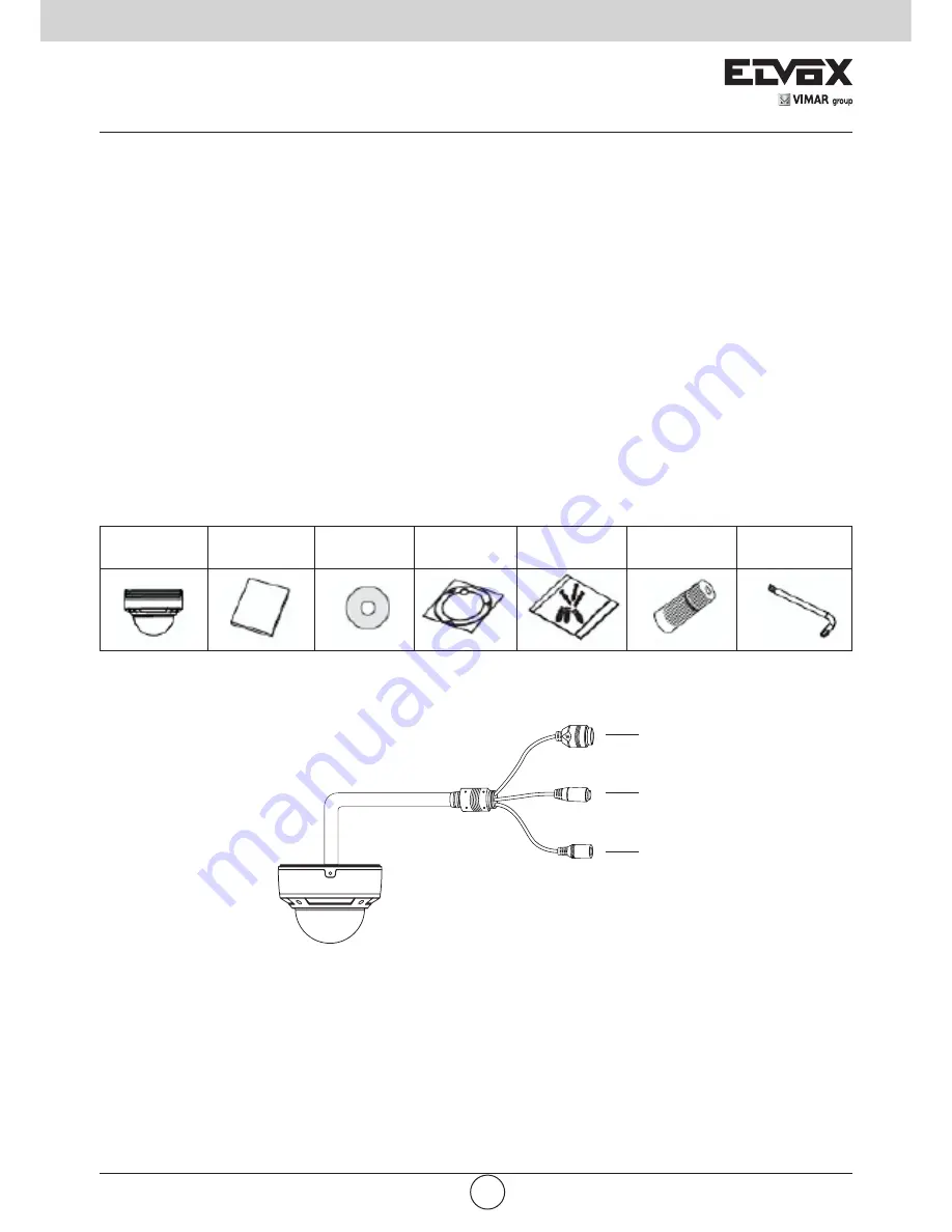
Camera

Quick start 

guide

CD

Template 

Screws

Water-proof 

cap

Screwdriver


Before use this product

-  Before operation, we strongly advise users to read this manual and keep it properly for using later.

-  This is product instructions not quality warranty. We may reserve the rights of amending the typographical errors, 

inconsistencies with the latest version, software upgrades and product improvements, interpretation and modifica-

tion. These changes will be published in the latest version without special notification.

-  When this product is in use, the relevant contents of Microsoft, Apple and Google will be involved in. The pictures 

and screenshots in this manual are only used to explain the usage of our product. The ownerships of trademarks, 

logos and other intellectual properties related to Microsoft, Apple and Google belong to the above-mentioned com-

panies. 

1 Introduction

Summarization

This IP-CAMERA (short for IP-CAM) is designed for high performance CCTV solutions. It adopts state of the art video 

processing chips. It utilizes most advanced technologies, such as video encoding and decoding technology, complies 

with the TCP/IP protocol, SoC, etc to ensure this system more stable and reliable. This unit consists of two parts: 

the IP-CAM device and central management software (short for CMS). The CMS centralizes all devices together via 

internet or LAN and establishes a sound surveillance system to realize unified management and remote operation to 

all devices in one network.

This product is widely used in banks, telecommunication systems, electricity power departments, law systems, fac-
tories, storehouses, uptowns, etc. In addition, it is also an ideal choice for surveillance sites with middle or high risks.

Check Package Content

Connection

Some models support 10m~20m IR distance; some hasn’t infrared lights that cannot support IR night vision. Please 
take the real object as standard. The below figures will introduce the appearance and function of interfaces.

CVBS  

Output: connect to an input analog device (monitor) 

DC12V:

 connect to power supply

LAN:

 network port (some models support PoE power supply)

2 Installation

2.1 Installation

The installation steps of Dome Camera are as follows:
Step 1- Loosen the screws with a hexagonal screwdriver and take down the back box as shown in the following left 
picutre.
Step 2- Paste the plotting sheet on the ceiling. Drill four holes and instert spiles in the ceiling as per the sheet. Use the 
screws to fix the bottomboard on the ceiling.

DC12V

Rout er

Computer

Network Cable

Netw

ork C

able

Network Cabl e

Network Cabl e

Netw

ork C

abl e

M odem

Internet

-

+

1-LAN

2-MIC

3-DC 12V

Summary of Contents for 46222.036.01

Page 1: ...Manuale per il collegamento e l uso Installation and operation manual 46222 036 01 Telecamera mini Dome IR IP 1 3 Mpx obiettivo 3 6 mm PoE IP IR mini Dome camera 1 3 Mpx 3 6 mm lens PoE ...

Page 2: ...stione centrale abbreviato in CMS Il CMS consente di centralizzare tutti i dispositivi via Internet o LAN e creare un impianto di sorveglianza affidabile che offre gestione unificata e attivazione in remoto di tutti i dispositivi in rete Questo prodotto è ampiamente utilizzato nelle banche nei sistemi di telecomunicazione siti di fornitura elettrica enti statali fabbriche magazzini centri urbani e...

Page 3: ...CAM Fase 2 Collegare la linea Internet all apparecchiatura o ai dispositivi di trasferimento Internet Fase 3 Collegare il cavo di alimentazione a una presa di rete Fase 3 Serrare le viti e installare la scatola posteriore 2 2 Installare l IP CAM su rete Ethernet I collegamenti del server video digitale sono illustrati di seguito Microfono DC12V Router Computer NetworkCable Network Cable Network Ca...

Page 4: ...ato Config immagine Saturazione Luminosità Colore Contrasto WDR Nitidezza NR Via IE e client end ROI Compressione audio G711A Interfaccia Internet RJ45 Uscita video No Audio Audio monodirezionale MIC IN x 1 RS485 No Ingresso allarme No Uscita allarme No Funzione Sorveglianza remota Browser IE controllo da CMS Utenti online 10 utenti supporta la trasmissione su più flussi in tempo reale Protocollo ...

Page 5: ... and reliable This unit consists of two parts the IP CAM device and central management software short for CMS The CMS centralizes all devices together via internet or LAN and establishes a sound surveillance system to realize unified management and remote operation to all devices in one network This product is widely used in banks telecommunication systems electricity power departments law systems...

Page 6: ... firstly Step 2 Internet line connect to Internet transfer equipment or devices Step 3 Connect power cable to a power outlet Step 3 Tighten the screws and install the back box 2 2 Install IP CAM to Ethernet Network The connection of digital video server is show below Microphone DC12V Router Computer NetworkCable Network Cable Network Cable Network Cable Network Cable M odem Internet Computer Inter...

Page 7: ...5 level CBR no limit Image config Saturation Brightness Crome Contrast WDR Sharpness NR Via IE and client end Audio compression G711A Interface Internet RJ45 Video out No Audio Unidirectional MIC INx1 RS485 No Alarm in No Alarm out No Function Remote surveillance IE browser CMS remote control Online user 4 users support multi stream real time transmission Network protocal TCP IP UDP DHCP NTP RTSP ...

Page 8: ...Viale Vicenza 14 36063 Marostica VI Italy www vimar com 49401023A0 00 16 04 ...

Reviews: