background image

15

6.4.3   Consulting the energy probe (if enabled)

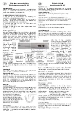
Fig. 11: Typical screen for consulting the energy probe

This option is used to consult data on the instantaneous power and energy consumed/generated 
by the system and measured instantly by the energy probe. 

CAUTION: Proper operation and proper consultation require:
• The energy probe 02960 to be powered and functioning
• The energy probe 02960 is properly interconnected with the circuit board 02915
• The clock of the timer-thermostat to be set correctly   
If these conditions are met, the indicator LED of the energy probe 02960 will flash "slowly" 
(1 flash every 2 seconds approximately). 

The 

measured power

 is the value measured by the energy probe 02960; the value shown is the 

sum of the (active) powers of all the active channels of the probe (eg, all 3 channels could be 
active, or only channel 1 or channels 1 and 3, etc.). 
The unit of measurement (W or kW) is displayed under the measured value. 
•  If the sum of the powers turns out to be 

consumed

 (i.e. absorbed by the energy supplier), the 

value is 

positive

 and the generation/consumption indicator is off.  

•  If the sum of the powers turns out to be 

generated

 (for example, the photovoltaic system is 

supplying power to the electricity grid), the value is 

negative

 and the generation/consumption 

indicator is on.

When consulting the power/energy data, the "consumption log" view provides a rough estimate 
of the consumption recorded in the last period. In particular, each horizontal group of dashes rep-
resents the year/month/day/hour depending on whether the word displayed is YEARS/MONTHS/
DAYS/HOURS respectively.

The current year/month/day/hour

 is highlighted by the group of flashing dashes while the 

previous

 and the 

next

 are represented by groups of dashes shown respectively to the 

left

 and 

right

 of the flashing group. 

Comparison ring with 

the average power

Indicator for 

production/consumption

Measured power

Unit of measurement

Button for consulting energy log

Summary of Contents for 02910

Page 1: ...Instructions manual Timer Thermostat 02910 Installer Manual ...

Page 2: ......

Page 3: ... 6 Antifreeze 23 7 7 Remote reduction 23 7 8 Remote auto 24 8 Settings menu 25 8 1 Operating mode setting 26 8 2 Setting the time and day of the week 26 8 3 Heating air conditioning setting 26 8 4 Unit of measurement setting 26 8 5 Daily program setting 26 8 5 1 Selecting the day of the week 27 8 5 2 Temperature selection 27 8 6 Temperature setting 28 8 6 1 Away temperature 29 8 6 2 Economy temper...

Page 4: ...2 8 12 Info about the device 33 8 13 Lock unlock PIN setting 33 9 Parameters table 34 10 Alarms 35 11 Cleaning the device 35 12 Installation rules 35 13 Regulatory compliance 35 ...

Page 5: ...user interface thanks to special views facilitates system management helping the user to oper ate while maintaining a state of energy saving Consultation of the energy consumption or generation carried out by connecting to the energy probe 02960 lets you monitor up to 3 separate phases with common neutral for a maximum of 10kW per phase The device will not activate deactivate loads depending on th...

Page 6: ...ingle wire or 1 multi wire cable conductor MAX 1 5 mm2 Length of the conductor max 100 m between the 2 terminals 4 3 Energy Probe 02960 For the timer thermostat to be able to communicate with the energy probe 02960 it is necessary to use the circuit board 02915 that is to be installed on the wall base Connect the circuit board 02915 and energy probe 02960 using a UTP CAT5E cable or better the RJ9 ...

Page 7: ...The energy probe can save the consumption data log for a very long time up to 3 years provided that its power supply is not interrupted for more than 7 consecutive days at each start the time must be reset by the timer thermostat If the probe should remain switched off for over a week the entire switch off period would be reduced in any case to a week at most with a loss of consistency in the log ...

Page 8: ...V 1 L N 3 L1 SENSOR ENERGY METER 02960 MADE IN ITALY CTRY OF MFG PAT PEND P A 38 32 N L D AT E C O D E L1 L2 N L L L N I CTRY OF MFG PAT PEND P A 38 32 N L D AT E C O D E I RS 485 Fig 3 Measurement of the total consumption of a system also with single phase loads distrib uted over multiple phases ...

Page 9: ...Y CTRY OF MFG PAT PEND P A 3 8 3 2 N L D AT E C O D E L N I RS 485 L1 N Fig 4 Measurement of net consumption or generation with a photovoltaic system installed In cases of generation via a photovoltaic panel fed into the national grid the probe will record a NEGATIVE value which corresponds to energy generation the opposite of consumption INVERTER ...

Page 10: ...DE L2 L1 N L N I CTRY OF MFG PAT PEND PA 38 32 N L DA TE CO DE I RS 485 Fig 5 Measurement of differentiable consumption and generation with a photovoltaic system installed Observe the direction of installation of the current probe S2 in cases of generation via a photovoltaic panel the probe will record a NEGATIVE value that corresponds to energy generation as opposed to consumption INVERTER ...

Page 11: ...1 5V AA batteries CAUTION In case of replacement dispose of batteries in the specific differentiated collection bins Fig 6 Changing batteries The battery charge status is shown as follows no icon battery charged flashing icon battery almost flat replace it fixed on icon battery flat the device will go OFF and it is no longer possible to switch to operation ...

Page 12: ... Fig 7 Graphical interface and buttons A Ring indicating consumption level and energy savings indicator B Battery charge status C Operating mode D Away E Confirm or energy log navigation F G Menu navigation and setting parameters H Back I Alternative viewing L Settings menu M AUTO programme temperature trends and consumption log ...

Page 13: ...ments that can be scrolled confirms the selected option activates the submenu if there is one or displays the next parameter digit After each confirmation the display shows the icon for approximately 1 s In addition if the timer thermostat is connected to the probe 02960 via the circuit board 02915 it will also be possible to enable its acoustic signal back or cancel exits the current screen menu ...

Page 14: ...g the PIN Timed manual operation Away Manual Nighttime reduction Antifreeze Switched off OFF Automatic operation Multi function input ON Alarm Air conditioning Heating Power Energy Energy consumption log Eco saving Buzzer beep Confirm Day of the week indicator Away temperature Economy temperature Comfort temperature ...

Page 15: ...information to display on the left hand side of the display If the right side always displays the measured temperature together with other data which will be explained below tapping in succession the button on the left hand side and in the program area will display the two following options 6 4 1 Clock daily program and Ecometer Fig 9 Typical view of the time and daily program This view is the def...

Page 16: ... program area will not be active Fig 10 Typical view of ecometer mode The set of icons called ECOMETER provides a general indication of the expected consumption facilitating energy saving The consumption forecast is given by a comparison between the currently set temperature value and a conventional average consumption defined in the device The ring of the level of consumption indicates the level ...

Page 17: ...f measurement W or kW is displayed under the measured value If the sum of the powers turns out to be consumed i e absorbed by the energy supplier the value is positive and the generation consumption indicator is off If the sum of the powers turns out to be generated for example the photovoltaic system is supplying power to the electricity grid the value is negative and the generation consumption i...

Page 18: ...tead of the instantaneous power displays the energy consumed or generated during the current day in this case the circular ring represents the level of consumption of the current day compared to the last 30 days If the dashes reach halfway around the ring it means that the consumption in the last 24 hours is in line with that of the last 30 days vice versa if the dashes exceed or are less than hal...

Page 19: ... 30 days The month 1M therefore represents the consumption recorded in the period from 30 days ago until yesterday The month 2M represents the consumption recorded in the period from 60 days ago until 31 days ago etc yearly consumption enables you to scroll one by one through the years prior to the current one the indices range from 1Y yearly consumption of the last year to 3Y yearly consumption o...

Page 20: ...erature level to avoid damage to pipework or prevent the temper ature from falling below a safety level In addition if the multi function input of the timer thermostat has been suitably configured you can remotely activate the following modes Remote reduction lets you vary the set points of MANUAL adjustment to obtain energy savings Remote activation lets you activate the system remotely setting A...

Page 21: ...active the icon is displayed above the temperature indicator Fig 14 Typical screen for Manual mode The set point can always be changed via or Fig 15 Manual set point setting The selection is confirmed by touching The and icons in the lower right corner indicate whether the system is operating in heating or air conditioning mode respectively icon illuminated system on ...

Page 22: ...ttime reduction in the environment For setting the automatic program see par 8 5 When AUTO mode is active the icon is displayed above the temperature indicator Fig 16 Typical screen for Auto mode By touching and you can temporarily change the ambient temperature setting it to a differ ent value to the one associated with the current time slot Confirming with it then goes into TIMED MANUAL mode The...

Page 23: ...arting from AUTO mode and is recognizable by the icon displayed above the temperature indicator Fig 17 Input screen in Timed Manual mode Using and you set the temperature and confirm with The next screen again using and lets you set the time for which the temperature you have just set is maintained Fig 18 Regulating the number of hours of Timed Manual mode Finally confirm with At the end of the se...

Page 24: ...he adjustment according to the away temperature setpoint The Away mode can only be activated by touching The display will show the away temperature setpoint for approximately 2 seconds Fig 19 Input in away mode showing the away temperature Mode activation is identified by the icon Fig 20 Away Mode To exit and return to the initial mode touch the button again ...

Page 25: ...2910 thermostats in different rooms of the same house Example Before going to bed using a simple switch all the thermostats in the house are set onto reduc tion at the same time This mode comes into operation when the multi function input is activated only if this has been suitably configured the multifunction input is activated solely when the timer thermostat before the activation is in Manual m...

Page 26: ... functions that can be performed by the user This mode comes into operation when the multi function input is activated see par 4 2 only if it has been suitably configured In this condition the display and the relevant buttons must not be used The Remote auto mode is identified by the and icons located simultaneously above the temperature indicator Fig 23 Typical screen in Remote auto mode ...

Page 27: ...s 1 operating mode setting 2 setting the time and day of the week 3 air conditioning heating setting 4 unit of measurement setting 5 daily program setting 6 temperature setpoint setting 7 calibration setting 8 and multi function input setting 9 OnOff PID temperature control algorithm setting 10 energy probe setting 11 buzzer beep setting 12 device info 13 lock unlock PIN setting Touching opens the...

Page 28: ...evice depending on the season winter summer heating air conditioning Using and select the desired operation and confirm with 8 4 Unit of measurement setting This menu lets you set the unit of measurement used for the temperature C or F Using and select the desired unit of measurement and confirm with 8 5 Daily program setting This menu lets you set or modify the time and daily program for the ambi...

Page 29: ...th the current time which is shown on the clock on the left This temperature highlighted by the blinking can be selected from away temperature T away economy temperature T economy comfort temperature T comfort The dashes blinking indicate the time slot that you are setting there are 24 groups of 3 dashes and each group corresponds to one hour of the 24 in the day The selected temperature will be a...

Page 30: ...ut making a copy of the day you have just set useful when switching between programming working days and holidays to finish programming Touch to confirm the selected option 8 6 Temperature setting This menu lets you set the temperatures and hystereses necessary for defining the temperature control set point used in the different operating modes In particular you can have setpoints for 1 and Away t...

Page 31: ...nomy temperature differs depending on whether you are in the heating or air conditioning mode 8 6 3 Comfort temperature The menu via and lets you increase decrease the value of the comfort temperature and The Tcomfort temperature can be defined as the comfort temperature that you want to reach during the hours when people are present in the rooms of the dwelling The comfort temperature differs dep...

Page 32: ... by the timer thermostat to make it equal for example to that of a sample thermometer CAUTION For correct calibration it is recommended to wait until the timer thermostat has been on for at least 1 hour in a room at constant temperature Tap to confirm your choice 8 8 Multi function input setting This menu is used to set the operating mode of the multi function input Via and you can select the foll...

Page 33: ... this algorithm switches the system on and off appropriately so there will be a gradual increase or decrease in the thermal or refrigerating power of the system itself To take full advantage of its performance it needs to be suitably calibrated according to the type of envi ronment and heating system in the light of this the following parameters must be set via the submenus that follow this select...

Page 34: ... value meas ured by that channel so even if physically there is a power other than 0 which runs through the disabled phase the probe will still display the value 0 8 10 2 Configuring the power threshold alarm The menu lets you set an overall power level i e the sum of all 3 channels read by the energy probe and on exceeding which the timer thermostat will emit an audible alarm warning This feature...

Page 35: ...phases of the energy probe 02960 U1 U2 and U3 indicate the voltages RMS read in the respective phases 1 2 3 displays the active power measured in the phases of the energy probe 02960 P1 P2 and P3 indicate the powers read in the respective phases 1 2 3 This view lets you see the consumption or production of each single phase rather than the sum of all three as a single value 8 13 Lock unlock PIN se...

Page 36: ...PID Period 10 30 minutes 1 min 20 min Unit of measurement tem perature Temperature unit C F C Temperature offset TE Offset temp 0 3 C 0 1 C 0 C Energy probe Enable Disable IN1 ON OFF ON Enable Disable IN2 ON OFF OFF Enable Disable IN3 ON OFF OFF Calibration IN1 0x000 0xFFF 0x001 0x400 Calibration IN2 0x000 0xFFF 0x001 0x400 Calibration IN3 0x000 0xFFF 0x001 0x400 Enable Disable Alarm ON OFF ON Ala...

Page 37: ...nnected after installing the optional interface 10 Alarms The system is able to generate and report alarm conditions related to monitoring the consumption of elec tricity For a description of the notifications see respectively paragraph 8 10 2 11 Cleaning the device The device featuring a display with capacitive buttons requires you to be gentle during the cleaning phase Avoid using aggressive pro...

Page 38: ...02910 installer 01 1406 VIMAR Marostica Italy Viale Vicenza 14 36063 Marostica VI Italy Tel 39 0424 488 600 Fax Italy 39 0424 488 188 Fax Export 39 0424 488 709 www vimar com ...

Reviews: