background image

NT00000534-KSCR-ECOWATT-08-18-28-38-52-AN-200625

INST R U C T IO N  M A NU A L
INST A LLA T IO N  |   W

IR ING  |   C O M M ISSIO NING  |   M A INT ENA NC E  |

AFNOR CERTIFICATION

ISO 14001

Environnement

AFNOR CERTIFICATION

I S O   9 0 0 1

Q u a l i t é

K SC R   EC O W A T T

®

0 8   /   1 8   /   2 8   /   3 8   /   5 2

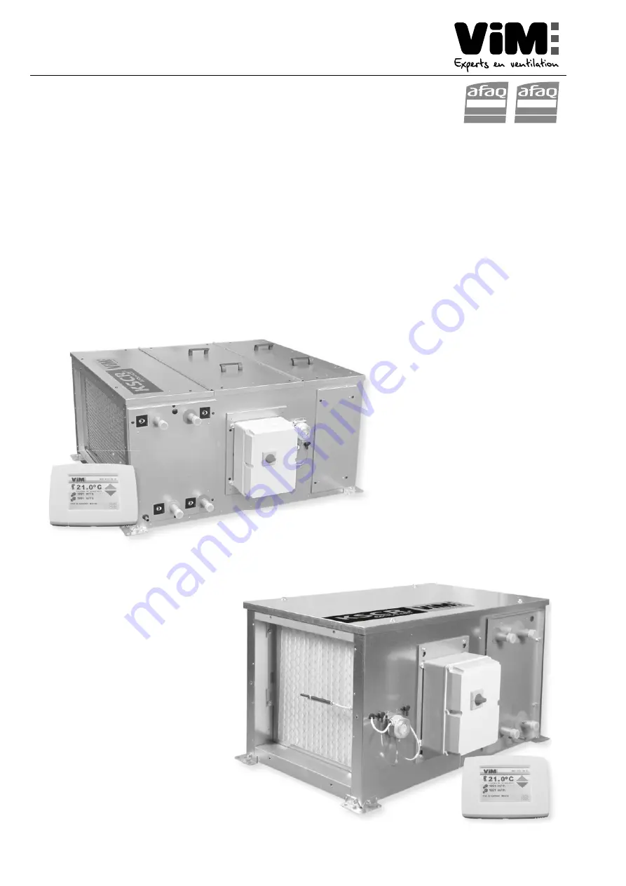
Compact controlled single flow air handling unit (AHU)

Summary of Contents for KSCR ECOWATT 08

Page 1: ...T IO N M A NU A L INST A LLA T IO N W IR ING C O M M ISSIO NING M A INT ENA NC E AFNOR CERTIFICATION ISO 14001 Environnement AFNOR CERTIFICATION ISO 9001 Q u a l i t K SC R EC O W A T T 0 8 1 8 2 8 3...

Page 2: ...ctrical heater 21 6 3 AHU power connection with water coil 22 6 4 Connecting an external unit 22 6 5 Control cabinet and connection 23 6 6 Connection of components to control the ventilation mode 23 6...

Page 3: ...tallation commissioning and maintenance of this product Once the installation is complete leave this manual in the machine for any later consultation The installation of this product installation conn...

Page 4: ...d 1 3 R e c e i p t St o r a g e In the event of any lack non conformity or total or partial damage of the delivered products the Buyer must note its written reservations on the carrier s receipt in a...

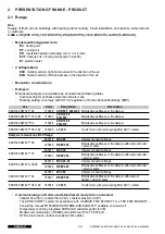
Page 5: ...70298 C D R 1 0 0 F 9 5 0 x 5 1 0 Motorisable antifreeze or fire damper KSCR ECOWATT 08 to 52 165385 LF 2 4 S On off motor with return spring 4Nm 24V 1 contact Dampers to mount on a BCC flange KSCR EC...

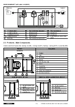
Page 6: ...filter F I2 Fresh air filter option D P 1 Fresh air filter pressure switch D P 3 Flow measurement B a t 1 Electrical heater ET D Touch display for control of the KSCR K SC R EC O W A T T w i t h w a t...

Page 7: ...Touch display for control of the KSCR 2 3 P r o d u c t s M a i n C o m p o n e n t s Version electrical heater EI heating coil EC cooling coil EF heating cooling ECF reversible ER M o d e l EI D e s...

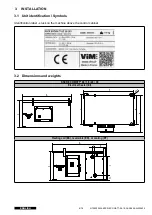
Page 8: ...tification Symbols Identification label stuck on the machine above the control cabinet 3 2 D i m e n s i o n s a n d w e i g h t s K SC R EC O W A T T 0 8 1 8 2 8 3 8 El e c t r i c a l h e a t e r EI...

Page 9: ...W A T T 2 8 1119 670 615 870 1140 690 K SC R EC O W A T T 3 8 1119 670 615 870 1140 690 Si z e W a t e r c o i l m m W e i g h t K g H J K L N P EI EC EF o r ER EC F K SC R EC O W A T T 0 8 8 9 2 1 0...

Page 10: ...nection A B C D i m e n s i o n s m m A B C K SC R 0 8 396 266 98 K SC R 1 8 2 8 3 8 546 495 98 K SC R 5 2 965 470 130 R a i n p r o o f h o o d P L H D i m e n s i o n s m m H L P K SC R 0 8 336 438...

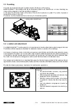
Page 11: ...side or outside of the buildings In all cases provide any ducts connection accessories anti vibration and anti freezing protection equip ment needed for the water coil In areas with a high snowfall ad...

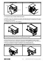
Page 12: ...ng legs setting Unscrew the eight self tapping screws fixed on the sides of the casing Re attach them to secure the 4 legs These will allow the cover fixing screws to be unscrewed without it falling I...

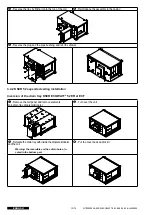
Page 13: ...2 K SC R 5 2 s u p e n d e d c e i l i n g i n s t a l l a t i o n In v e r s i o n o f t h e d r a i n t r a y K SC R EC O W A T T 5 2 ER e t EC F Remove the coil panel and remove elements coil drai...

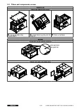
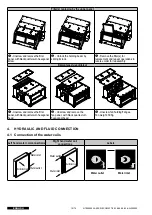
Page 14: ...8 F i l t e r s a n d c o m p o n e n t s a c c e s s H Upper panel dismantling 4 screws M8x25 Unlock filter s by pulling onto the sliding rail Remove the filter s K SC R 5 2 P a n e l s a n d a c c...

Page 15: ...ck quarter turn hexagonal head Unscrew fan holding flanges Fan weight 30Kg 4 HY D R A U LIC A ND F LU ID C O NNEC T IO N 4 1 C o n n e c t i o n o f t h e w a t e r c o i l s Le f t h a n d w a t e r...

Page 16: ...s o r A change over thermostat THCO is to be installed on the hydraulic network and connected to the elec trical cabinet of the unit It allows mixing valve control to be inverted in installations wit...

Page 17: ...o n o f t h e d u c t s The ducts should not impose any mechanical constraints on the unit Check that the fan motor is not accessible from the connection line protection by the connection duct or a st...

Page 18: ...i o n KSCR ECOWATT 132105 SP R D B 8 0 0 Pressure sensor in housing 0 800 Pa 0 5 4 5 V SPRD Accessory 132143 K T P R Kit of 2 pressure sensors screw 2 m of translucent tube Pressure sensors registerin...

Page 19: ...60 1 Phase 230V 193 1 5 1 Phase 230V 6 000 2x3 kW 26 1 K SC R 0 8 EI T r i 2 649 50 60 1 Phase 230V 193 1 5 3 Phases 400V N 9 000 3x3 kW 13 K SC R 0 8 EC EF ER 2 649 50 60 1 Phase 230V 193 1 5 K SC R...

Page 20: ...5 2 EI 3 Phases 400 V N 26 38 K SC R 5 2 EI 3 Phases 400 V N 38 55 K SC R 5 2 EI 3 Phases 400 V N 50 73 K SC R 5 2 EC ER EC F 3 Phases 400 V N 2 3 KSCR ECOWATT EI 08 6 kW single phase Power reducible...

Page 21: ...for the accessories The damper servomotors are powered by the power sup ply to the KSCR control at 24 V K SC R EC O W A T T 0 8 1 8 2 8 3 8 M AHU power supply Accessory damper driving Accessory damper...

Page 22: ...per driving Fresh air Supply air M M M 6 4 C o n n e c t i n g a n e x t e r n a l u n i t K SC R v e r s i o n A d d i n g a n e x t e r n a l h e a t i n g o r r e v e r s i b l e c o i l 0 1 0 V A...

Page 23: ...t i o n o f c o m p o n e n t s t o c o n t r o l t h e v e n t i l a t i o n m o d e M a i n c o m p o n e n t s Terminals not present for water coil units 1 5 13 23 25 31 35 41 45 A01 9 ON 3 7 11 1...

Page 24: ...e signal sent by the external pressure sensor of the extractor A c c e s s o r i e s Terminals not present for water coil units 1 5 13 23 25 31 35 41 45 A01 9 ON 3 7 11 15 21 27 33 37 43 60 D V A02 A0...

Page 25: ...31 35 41 45 A01 9 ON 3 7 11 15 21 27 33 37 43 60 D V A02 A03 A04 A05 A01 A02 A03 A04 A05 BREA DAD S4T1 24VDC G0 GND OX 08 Fire damper with spring back actuator C R DAD The DADs and sensors are access...

Page 26: ...ent for water coil units Reversible coil valve Heating cooling Y1 1 2 5 3 A01 27 Cooling coil valve Y3 1 2 5 3 A03 Brown Red Black THCO Change Over G0 GND 24VDC Not used G0 GND 24VDC Not used 24VDC No...

Page 27: ...to connect inside of the unit The ETD control is IP30 and is exclusively reserved for use indoors to be protected from any humidity It is equipped with an internal temperature sensor that can not be...

Page 28: ...sor cone outlet Supply fan command Extract fan command Electrical heater over heating alarm External setpoint CVF 1 5 13 23 25 31 35 A01 9 ON A02 A03 A04 A05 3 7 11 15 21 27 33 37 A01 A02 A03 A04 A05...

Page 29: ...e sensor cone outlet Supply fan command Extract fan command Electrical heater over heating alarm External setpoint CVF 24VDC power supply 0V G0 power supply 24VDC G0 Internal use Customer power supply...

Page 30: ...w pressure switch DI3 25 24 Vdc Alarm for overheating of electrical heater DI4 27 24 Vdc Change over sensor DI5 31 24 Vdc External request for Start Stop DI6 33 24 Vdc External request for LS HS DI7 3...

Page 31: ...ructions 1 2 Safety Guidelines page 4 In metropolitan France this service can be provided by VIM and its qualified providers C o n t a c t u s It can only occur once the installation and the electrica...

Page 32: ...sensor COP Mode Management of flows according to time periods clock BOOST function by external contact STOP function by external contact C o n t r o l o f t h e i n t e r n a l w a t e r c o i l s Adj...

Page 33: ...K 8 7 9 4 5 3 2 1 Enter PIN code 1111 Cancel Enter PIN code 1111 and select OK Setting Ventilation mode Select the control mode Main screen Pass word Control mode adjustement 6 0 Menu screen Menu CAV...

Page 34: ...ccess to adjustement menu Menu Menu screen Working mode selection Installer parameter Setting Ventilation mode CAV COP VAV Read the alarm Alarme Maintenance needed Display parameters Display setting E...

Page 35: ...orking mode COP COP Variable air flow working mode VAV VAV Constant air flow working mode CAV CAV Constant supply air temperature control with outdoor air compensation Constant supply air T control T...

Page 36: ...configuration menu via password 1111 enables The selection of the Low Speed and High Speed flow rates of the fan The night time setpoint value of the fan CAV CAV Supply Low speed High speed Night spee...

Page 37: ...400 1000 1400 2000 10 1400 1600 1200 1000 1800 Example of use Connection of a SCO2 sensor with a measurement range of 0 2000 ppm 0 10 V To use the range 400 1400 ppm you must select Vmin 2 V and Vmax...

Page 38: ...ate on which network the pressure sensor is placed see 5 2 2 Differ ential pressure sensor Operating in COP Constant Pressure page 18 The pressure setpoint is entered manually in Pa Ventilation mode R...

Page 39: ...A single PI control loop is used See 5 2 Connection of the accessories page 18 8 6 1 M a i n t a i n i n g a c o n s t a n t s u p p l y t e m p e r a t u r e Parameter Constant supply airT C Heating...

Page 40: ...ntenance needed Menu screen Select Temperature menu Menu Temperature Ventilation control 21 0 C Desired S P Extract T 21 9 C 10 8 C Room T Constant supply air temperature 20 9 C Supply T Pass word OK...

Page 41: ...am Advanced settings Welcome screen Sub menu Centrale simple flux 2012 11 12 Systeme Fonct Normal C 24 0C R 17 8C Running mode Temperature Air control Time settings Access rights In the hourly menu be...

Page 42: ...speed Sunday Per 1 00 00 00 00 Per 2 00 00 00 00 Normal speed Holidays Per 1 00 00 00 00 Per 2 00 00 00 00 The ranges are programmed either day by day or by copying either the same programming from Mo...

Page 43: ...Cooling AO4 SAF AO5 1 5 Free AI DI UI AO DO DO Digital output DO1 NC SAF frequency DO2 NC HS DO3 NC SAF frequency DO4 NO recirc damper DO5 NO 3rd heating step DO6 NO 2nd heating step DO7 NO heating P...

Page 44: ...ustement program O K 8 7 9 4 5 3 2 1 Enter PIN code Cancel 1111 Enter PIN code 1111 and select OK Setting Ventilation mode Select next screen Menu screen Pass word Control mode adjustement Control mod...

Page 45: ...eabove InCAVorVAVmode theVASpressuresensorallowsairflowcontrolandreading InCOPmode theVASpressuresensorallowspressureregulation Inthismode theVAS2pressuresensorallowsairflowreading Fillintheoperatingr...

Page 46: ...D 35 AI4 34 AI3 33 Agnd 32 AI2 31 UI1 30 Agnd 17 D07 16 D06 15 D05 14 D04 13 D03 12 D02 11 D01 10 GD0 4 C 2 G0 1 G TCP IP 45 UI4 44 UI3 43 Agnd 42 UI2 41 UI1 40 AGND 35 AI4 34 AI3 33 Agnd 32 AI2 31 UI...

Page 47: ...es Activate No 2 min Title PreloadedVtc files Activate Yes VentilationVim Choose Configuration Standard Accept change No VentilationVim Choose Configuration KSCR DR 2019 Accept change No VentilationVi...

Page 48: ...could be set di rectly on the last windows of the quick configuration menu The address by default is 1 if few units are connected the address of each one must be different from the others possible add...

Page 49: ...254 209 126 IP 192 168 001 234 Subnet mask 255 255 255 000 Tochangetheaddressclickon ModifythedifferentpartsinHighlightingwiththedirection arrowsandvalid Default gateway 192 168 065 001 DNS 0 0 0 0 Te...

Page 50: ...P mode with pressure transmitter on supply air duct Value of Pa mesurement on supply air fan nozzle Air flow is obtain by calculationl Air flow K P Coef K value corresponding to the unit P read value...

Page 51: ...nt temp rature in constant supply air Temperature 0 999 value 0 999 means 0 99 9 C 0 off Saison change over 40230 R W Change over control mode 0 heating mode 1 cooling mode 2 auto 0 1 or 2 W O R K ING...

Page 52: ...evalueinHighlighting Speed 9600bps Max master address 127 Tochangespeedclickon ModifythevalueinHighlightingwitharrowandvalid Temperature Air control Time settings Acces rights Log on enter password Ac...

Page 53: ...BBMD address Tochangethename clickon ModifythevalueinHighlighting Device ID low 2640 Device ID high 0 10000 TochangetheIDlowandhighvalueclickon ModifythevalueinHighlighting TochangetheUDPport clickon...

Page 54: ...h on 1 2 3 4 A01 A03 A04 23 24 31 32 D I3 D I4 D I2 D I1 A gn d A O 1 A O 3 A O 2 G G 0 C D O 4 D O 3 D O 1 D O 2 G 0 A gn d A gn d A gn d A gn d D O 5 D O 7 D O 6 D I7 D I8 D I6 D I5 A O 5 A O 4 33 3...

Page 55: ...NT00000534 KSCR ECOWATT 08 18 28 38 52 AN 200625 55 76 ENGLISH Click on the icon to select the type of connection Select TCP IP...

Page 56: ...the relevant CORRIGO The name and the serial number of the CORRIGO appear Select the auomaton to connect if there are several on the network and press OK Go back to the previous screen the selected u...

Page 57: ...200625 57 76 ENGLISH Check Obtain an IP address automatically by DHCP and click on Load the TCP IP settings to load the information on the CORRIGO Synchronising the CORRIGO with the PC allows recover...

Page 58: ...R ECOWATT 08 18 28 38 52 AN 200625 ENGLISH 58 76 Update the E tool Import the parameters from the CORRIGO A T T ENT IO N D O NO T C LIC K O N U P D A T E T HE C O NT R O LLER Activation of the BACnet...

Page 59: ...work By default the last 4 digits of the CORRIGO serial number can be assigned Once this operation is completed the changes made on E tool with the CORRIGO must be synchronized Place the mouse cursor...

Page 60: ...76 Go to Communication port settings and a window appears on the screen Click on Use the following IP Settings and enter the information provided by the customer in the corre sponding boxes for examp...

Page 61: ...IP address and the last 3 are specific To validate click on Load the TCP IP settings The CORRIGO is ready to be installed on the desired TCP IP network and to communicate in BACnet The file for the i...

Page 62: ...us for the procedure to follow The connection of the CORRIGO regulator to the TCP IP network is carried out with a network cable to the RJ45 connection 1 2 3 4 A01 A03 A04 23 24 31 32 D I3 D I4 D I2 D...

Page 63: ...on the following icon in the office The following screen appears On the first screen choose the type of CORRIGO that is connected and select from the list Corresponding to the CORRIGO V3 the 3 ports u...

Page 64: ...investigation is then conducted of any connected CORRIGO The names and the numbers of the CORRIGOs appear select the auomaton to connect if there are several on the network and press OK Note the Ethe...

Page 65: ...by the network administrator in the corresponding boxes for example IP Address 192 168 010 100 Sub net mask 255 255 255 000 Default Gateway the first 9 digits identical to those of the IP address and...

Page 66: ...ENGLISH 66 76 The CORRIGO is now configured for your network From your browser you can now type the controller IP address to be connected to the controller web page For the example above type 192 168...

Page 67: ...e r v i c e consultation and modifications to the values Click on Run the application to display the following window which represents the current status of the unit in real time The 2nd tab includes...

Page 68: ...8 28 38 52 AN 200625 ENGLISH 68 76 The 3rd tab allows consultation of the alarms The 4th tab allows viewing the status of the inputs outputs of the controller For more details please see 9 3 Control o...

Page 69: ...AN 200625 69 76 ENGLISH The 5th tab allows programming a schedule of hours of automatic operation The 6th tab includes the proportional and integral values as well as the trigger settings for some al...

Page 70: ...ective Equipment for any operation Respect the danger signs present on the various access doors Li v e e l e c t r i c a l e q u i p m e n t R o t a t i n g m a c h i n e r y Potentially flammable dus...

Page 71: ...Check the operation Sensors Check the operation settings Check the operation settings Flexible sleeves Check they are correctly mounted and sealed Replace if necessary Fresh air intake extract grill...

Page 72: ...the extract air sensor 51 Ambient 1 sensor error Malfunction of the ambient 1 sensor 53 Temp sensor error AE Not used here 55 Pressure sensor error AN Malfunction of the pressure sensor 56 Pressure se...

Page 73: ...fan Switch off the electrical supply at the primary circuit breaker Remove the cover Disconnect the power and control connection plugs at the side Disconnect the pressure sensor Unscrew the two screw...

Page 74: ...e base Hold the base and remove the cover Grip the battery and gently pull it upward until it leaves its housing Take a new battery and slide it in the support Pay attention to the direction of instal...

Page 75: ...4 Plug fan PFOI 52 Plugfan ECM D310 1800W Tri KSCR 52 068364 Cooling coil BAT EG 4R KSDA 10 KSDR KSCR 08 Cooling coil 068365 Heating and reversible coil BAT EC EG 3R KSDA 10 KSDR KSCR 08 Heating rever...

Page 76: ...to improve its equipment the manufacturer re serves the right to make any technical changes without notice V IM Le s p r s d e M g y Su d SO U D A N C S 6 0 1 2 0 7 9 4 0 1 ST M A IX ENT L EC O LE C...

Reviews: