VCSO210SS
24
1. Disconnect the power supply cord.
2. Remove the outer case cabinet, referring to
“OUTER CASE REMOVAL”.
3. Open the oven door and block it open.
4. Remove the one (1) screw holding the side angle to the
back plate.
5. Remove the two (2) screws holding the back plate to the
top rear angle.
6. Remove the three (4) screws fixing the back plate.
7. Now, the back plate with exhaust cover is free.
1. REMOvAL
1. Disconnect the power supply cord.
2. Wait for 60 seconds to discharge the high voltage ca-
pacitors of the inverter unit.
3. Remove the outer case cabinet, referring to
“OUTER CASE REMOVAL”.
4. Remove the dew tray
5. Disconnect the 12-pin connector of the control panel
harness.
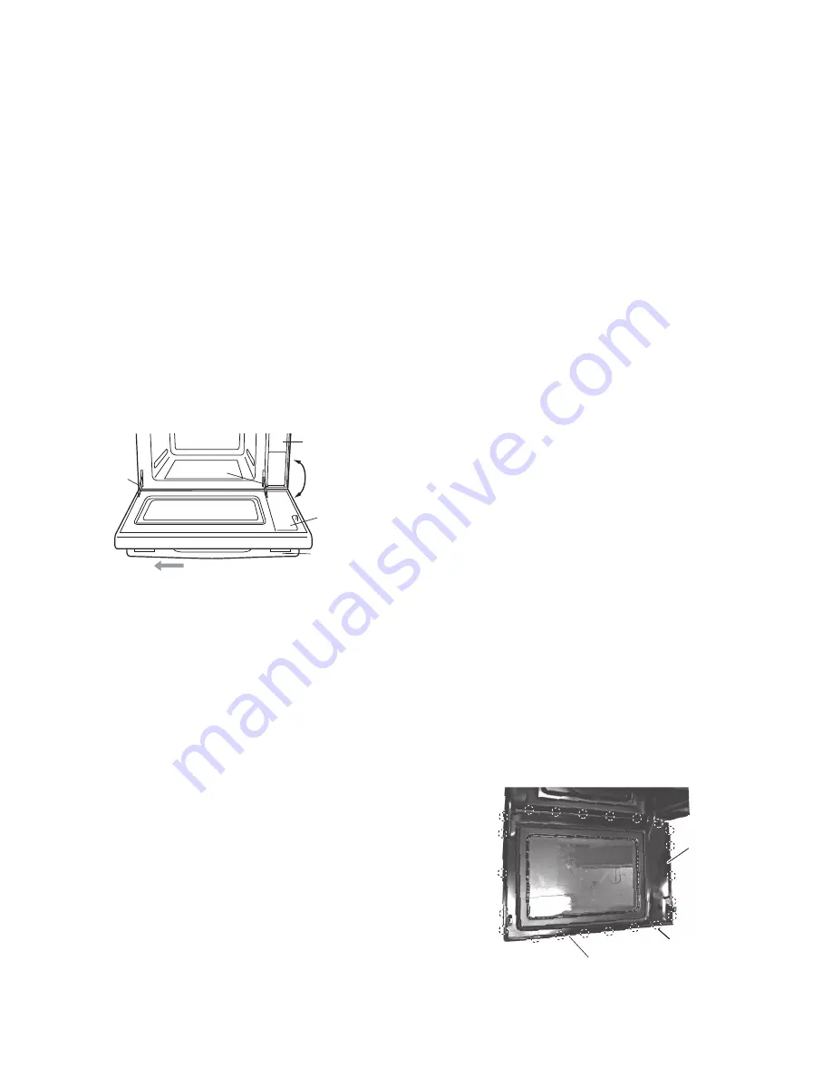
6. With the door open 45°, push the door cam down and
back, then slowly open the door to remove it.
7. With the door open more than 106°, slide the door left
from the hinge pin slot to remove it.
NOTE: Be careful not to make the 12-pin harness caught
in the square hole of the oven.
Be careful when installing the door, since the door
cam is eas- ily pulled in the back of the oven.
After replacing the door or loosening/removing
the hinge screws, make sure to adjust the door.
2. REiNSTALL
1. To facilitate reinstallation, first put the hinge pin in the
right hinge.
CAUTiON:
If bent, the comb-shaped teeth should be
straighten (other-wise, microwave leakage may
result.)
After replacing or repairing the door, ensure that
there is no microwave leakage (otherwise,
microwave leakage may result).
Always make latch adjustment (otherwise, mal
function may result)
3. After any service to the door
1) Make sure that the door sensing switch, the secondary
interlock switch and the monitor switch are operating
properly. (Refer to chapter page 26 ‘switch adjustment’)
2) An approved microwave survey meter should be used to
assure compliance with proper microwave radiation
emission limitation standards.
Panel R
Handle
Slide to left
Door Cover
Door Cam
Door Cam
106º
DOOR COvER REMOvAL
1. Disconnect the power supply cord.
2. Wait for 60 seconds to discharge the high voltage capacitors
of the inverter unit.
3. Put a putty knife (thickness of about 0.5mm) into the gap
between the door cover and the door frame (for tab positions,
refer to photo). First disengage five(5) tags on the right side,
five(5) tags on the left side, and six(6) tags on the front side.
4. Remove the door packing from the door cover.
5. Lifting the front of door cover disengages six (6) tags on the
back side.
Following the above steps 3, 4 and 5 can remove the door cover
without breaking it.
NOTE:
* Embed the entire circumference of the door packing in the
door cover and then fit the door packing with the door frame.
* After assembling, press the entire circumference of the door
packing so that the door packing is in a uniform condition
without protrusion.
* Be careful not to damage the surface.
* After assembling, check that there is no microwave/steam
leakage from the door.
Door frame
Tab positions
Door cover
DOOR ASSEMBLY REPLACEMENT
BACK PLATE REMOvAL


