background image

To avoid risk of electrical shock, personal injury, or death, disconnect electrical power source to unit, unless test 

procedures require power to be connected. Discharge capacitor through a resistor before attempting to service. 

Ensure all ground wires are connected before certifying unit as repaired and/or operational.

WARNING

!

Disassembly

©2012 Viking Preferred Service

27

Defrost  Heater

The unit uses a heater to help remove ice 

build- up during the defrost cycle. When the 

defrost terminator closes, voltage is supplied 

to the heater via the control board.
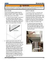
1.  To access the defrost heater, (see freezer 

fan access section). With back cover 

removed, the defrost heater is clipped to 

the bottom of the evaporator. Remove the 

clips, remove the heater, disconnect the 

wiring, and replace/repair as needed.

2.  With the main power switch OFF, the 

defrost Heater can be tested by removing 

the orange wire off of terminal E6 on the 

HV board. Using an ohm meter, check the 

brown wire and Neutral and you should 

read approximately 30 Ω. During the 

defrost cycle line voltage passes through 

the Defrost Terminator the into terminal 

E5 (orange wire). With the defrost heater 

relay activated, the voltage exits the HV 

board from Terminal E6 (orange) to the 

heating element. If voltage is present at 

E5 but not at E6, then the Defrost relay is 

open. If there are 0 volts at E5, then the 

terminator is open.

Defrost  Terminator

The defrost terminator is a bimetal switch 

that is normally open. Below 20+/-8.5 ˚F, 

the terminator is closed. In order to test, first 

switch the main power switch to “OFF”,  then 

locate the brown wire on E5 of the HV board. 

Unplug the wire and check for continuity 

between the brown wire and the black wire 

at E10. In the defrost cycle, this circuit will 

supply line voltage to the defrost relay.
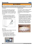
1.  To access the defrost terminator (see 

freezer fan access section). With rear 

cover off, defrost thermostat is located 

on the left side of the evaporator. Un-clip 

the terminator, disconnect wiring, repair/

replace terminator.

Summary of Contents for Quiet Cool VCFB5301

Page 1: ...s to be used by qualified appliance technicians only Viking does not assume any responsibility for property damage or personal injury for improper service procedures done by an unqualified person This...

Page 2: ...9 Program Mode A 29 Display Frz Temperature 29 Defrost mode selection 29 Conventional defrost time adjustment CRTD 29 Compressor low speed frequency 30 Adjust Cut In Hysteresis 30 Adjust Cut Out Hyste...

Page 3: ...ill be preceded by the safety alert symbol and the word DANGER WARNING or CAUTION These words mean IMMEDIATE HAZARDS WHICH WILL RESULT IN SEVERE PERSONAL INJURY OR DEATH Hazards or unsafe practices wh...

Page 4: ...rovided This appliance is equipped with a power supply cord having a 3 prong grounding plug To minimize possible shock hazard the cord must be plugged into a mating 3 prong grounding type wall recepta...

Page 5: ...36 Wide Refresh Right Hinge Stainless Model Numbers Serial Numbers 02 15 12 R1000264 Month Day Year of Manufacture Serial Number General Information 2012 Viking Preferred Service 5 The serial number...

Page 6: ...ty seconds the digital display will change to numbers indicating temperature in the freezer compartment along with the word FREEZER and degrees Fahrenheit Electronic Temperature Settings Settings and...

Page 7: ...FRZ extinguishing from display Max Frz is enabled by pressing and releasing the ACTIVATE CONTROLS pad and then Pressing MAX FRZ When FAST COOL is selected by pressing the pad FAST COOL is illuminated...

Page 8: ...imultaneously Continue holding until three beeps are heard The display will revert to normal operation To enter Forced defrost first press and release ACTIVATE CONTROLS then press and hold HIGHER pad...

Page 9: ...h will remain illuminated whether the door s are open or closed it will not change state Sabbath mode is used to control the refrigerator without interior lights LED display changes and enunciators Al...

Page 10: ...d FAST COOL will light up enabling the fast cool function which changes the freezer set point to max frz and the ref set point to max ref for a fac tory default of 2 hours Press FAST COOL pad A second...

Page 11: ...ned by resistance levels of freezer or refrigerator thermistors Freezer Thermistor NTC As temperature decreases resistance increases As temperature increases resistance decreases Note Open thermistor...

Page 12: ...here grille was removed with ratchet to get to hinge bolts 2 Loosen the four hinge bolts Adjust door 3 Reverse procedure for reinstallation Door Hinge Adjustment Removal of the upper grille assembly a...

Page 13: ...mage Height Adjustment Removal of the kickplate allows access to rollers and stabilizing legs for height adjustment 1 Remove lower kickplate screws using a Phillips screwdriver 2 Remove upper kickplat...

Page 14: ...es are connected before certifying unit as repaired and or operational WARNING ACTIVATE CONTROLS LOWER HIGHER FRZ TEMP FAST COOL MAX FRZ ALARM OFF DISPLAY OFF FREEZER SAB SHOW FAST COOL MAX FRZ MAX RE...

Page 15: ...ol boards 1 To access the control panel remove the upper air grill assembly see Upper Grill Removal section remove 2 screws securing the control panel Control Panel Screws 2 Pull control panel from se...

Page 16: ...Reverse procedure to reinstall Overlay Switch The unit uses an overlay switch to communicate user input to the control boards The overlay connects to the control board via a ribbon cable 1 To replace...

Page 17: ...onents 1 To access the high voltage board remove the upper air grill assembly and control panel see Air Grill and Control Panel Removal sections Page 15 2 Compress plastic standoffs securing the high...

Page 18: ...nnect is now accessible on the right side 2 Verify contacts 4 5 open when the switch is in the 0 position and contacts 4 5 close when in the position 120 VAC should be measured when in the 0 position...

Page 19: ...he condenser fan is located in the upper machine compartment of the unit 120 VDC is supplied to the fan when the Compressor Condenser Fan relay closes to E4 on the High Voltage Board 1 To access the c...

Page 20: ...es require power to be connected Discharge capacitor through a resistor before attempting to service Ensure all ground wires are connected before certifying unit as repaired and or operational WARNING...

Page 21: ...er to let air circulate will help make ice faster After the ice forms the ice maker continues to wait until it reaches 15 F before it starts the harvest cycle This ensures that the ice is solid in all...

Page 22: ...on T Thermostat connection L L1 hot side of line voltage V Water valve connection Place a 14 gauge jumper wire across test points T and H With hands clear of the ice maker manually close the freezer d...

Page 23: ...creen in water ll valve or particles of sand can keep valve from seating properly If water valve does not operate properly the following could occur no ice production small or hollow ice cubes ooding...

Page 24: ...ctrically open this indicates an overheat in the ice maker and the ice maker must be replaced TCO Freezer Thermistor The freezer thermistor is a device that reads freezer temperatures The temperature...

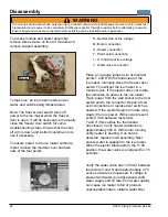
Page 25: ...to pull air over the evaporator coil and circulate it throughout the unit The 36 unit uses two fan motors to pull air over the evaporator coil and circulate it throughout the unit Freezer Fan Note Th...

Page 26: ...nd wires are connected before certifying unit as repaired and or operational WARNING Disassembly 26 2012 Viking Preferred Service 5 Remove screws securing freezer fan disconnect wiring and repair repl...

Page 27: ...rminal E6 on the HV board Using an ohm meter check the brown wire and Neutral and you should read approximately 30 During the defrost cycle line voltage passes through the Defrost Terminator the into...

Page 28: ...isconnect wiring and repair replace as necessary Water Valve The All Freezer uses a 120 VAC 35 watt valve to supply water to the ice maker 1 To access remove the lower access panel and the valve is ac...

Page 29: ...es on the freezer thermistor as shown in illustration next column Display Frz Temperature Unit is shipped in Adaptive defrost mode this can be changed to Conventional defrost mode using the following...

Page 30: ...is value can be set in Mode A as a separate adjustment or can be set automatically in Mode C when selecting model code where several control values are set by eeprom Table 1 Page 39 lists eeprom value...

Page 31: ...s the display will change to COH To exit the cut in adjustment press and release ACTIVATE CONTROLS one time which will result in PrA being displayed You are now back in Mode A Adjust Cut Out Hysteresi...

Page 32: ...is now in Program Mode B see illustration below Adjust Freezer Temperature Offset Freezer temperature offset is a predetermined value based upon model of refrigerator This value can be set in Mode B...

Page 33: ...ious actions Adjust Compressor High Frequency This adjustment is not a field adjustment and should not be performed by technicians This is a factory only adjustment If you see CHF in the display immed...

Page 34: ...or three seconds until you get three audible beeps Return to your previous actions Exiting Mode B ACTIVATE CONTROLS To exit Mode B and retain any changes made in system up to this point you must press...

Page 35: ...nd releasing HIGHER and LOWER pads will increase or decrease the set point which should be set at 7o F MAX FRZ LOWER Adjust Freezer Lower Temperature Limit While in Mode C press and hold MAX FRZ and a...

Page 36: ...up to this point you must press and release ACTIVATE CONTROLS one time the display changes to Prb This signifies that the changes were written to the eeprom and that the system has left Mode C and re...

Page 37: ...mit temperature as described in the appropriate zone above Then pressing and releasing ALARM OFF oncewillclearthe HIGHTEMP offthescreen and the zone indicator will stop flashing 2 Open Thermistor Alar...

Page 38: ...Power Loss Alarm If the control experiences a power loss condition and power is restored the Power Loss alarm is displayed This consists of the POWER indicator beingflashedonandoffalongwiththetemperat...

Page 39: ...ut o F FRZ Cut In o F FRZ Cut out o F REF user default temp REF user default temp BM36 136 65 9 0 6 6 7 8 38 0 SxS42 342 75 6 2 6 6 7 7 38 0 SxS42D 242 75 8 4 6 6 7 7 38 0 SxS48 348 75 4 5 6 6 7 7 38...

Page 40: ...circuit 2 Compressor winding open circuit Check compressor inverter cable connection Check compressor winding resistances among the 3 terminal hermetic pins If resistances are within specifications an...

Page 41: ...5 VAC Compressor Con denser Fan E4 E11 115 VAC Defrost Terminator closed E5 E11 0 VAC Defrost Terminator open E5 E11 115 VAC Defrost Heater E6 E11 115 VAC Ref door switch top right light E7 E11 115 VA...

Page 42: ...26 V p p to 34V p p ref P4 12 See Note 1 below P4 5 DC Fan enable 17 8 vdc 38 vdc ref to chassis grnd DC P4 6 Defrost termination 17 8 vdc 38 vdc ref to chassis grnd See Note 2 below P4 7 Evaporator f...

Page 43: ...Water supply Verify freezer temperature Verify the arm is in the ON position Replace Ice Maker Verify valve operation Verify water supply Freezer too warm AF Model Control setting Door seal Dirty cond...

Page 44: ...er at connector socket Determine discontinuity by tracing power No power to water valve Determine discontinuity by tracing power Ice Maker No Water AF Models Action No water to refrigerator Turn on su...

Page 45: ...roblems Action Raised shut off arm Lower shut off arm to ON position Broken or bent shut off arm Repair arm or replace ice maker Shut off arm stuck or obstructed Remove obstruction Ice maker not level...

Page 46: ...ocedures require power to be connected Discharge capacitor through a resistor before attempting to service Ensure all ground wires are connected before certifying unit as repaired and or operational W...

Page 47: ...it unless test procedures require power to be connected Discharge capacitor through a resistor before attempting to service Ensure all ground wires are connected before certifying unit as repaired and...

Page 48: ...Schematic 48 2012 Viking Preferred Service 30 All Freezer Schematic Upper Section...

Page 49: ...Schematic 2012 Viking Preferred Service 49 30 All Freezer Schematic Lower Section...

Page 50: ...Schematic 50 2012 Viking Preferred Service 36 All Freezer Schematic Upper Section...

Page 51: ...Schematic 2012 Viking Preferred Service 51 36 All Freezer Schematic Lower Section...

Page 52: ...Wiring Diagrams 52 2012 Viking Preferred Service UPPER SECTION WIRING 30...

Page 53: ...Wiring Diagrams 2012 Viking Preferred Service 53 LOWER SECTION WIRING 30...

Page 54: ...Wiring Diagrams 54 2012 Viking Preferred Service UPPER SECTION WIRING 36...

Page 55: ...Wiring Diagrams 2012 Viking Preferred Service 55 LOWER SECTION WIRING 36...

Reviews: