


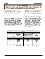


To avoid risk of electrical shock, personal injury, or death, disconnect electrical power source to unit, unless test
procedures require power to be connected. Discharge capacitor through a resistor before attempting to service.
Ensure all ground wires are connected before certifying unit as repaired and/or operational.
WARNING
!
DANGER
!
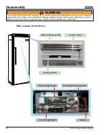
Disassembly
18
©2012 Viking Preferred Service
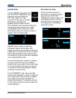
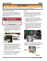
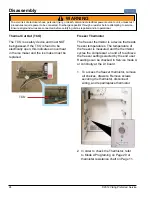
Power Disconnect Switch
The unit has a rocker switch, located in the
upper right corner of the unit, that allows
power to the unit to be turned “OFF” without
removal of the unit.
ON/OFF switch has 120 vac connected
to one side of switch at all times, remove
power with circuit breaker box when
removing switch.
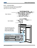
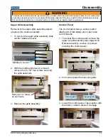
1. To access the power disconnect switch,
remove the upper air grill assembly (see
Air Grill Removal section, Page 14). The
power disconnect is now accessible on
the right side.
2. Verify contacts 4-5 open when the switch
is in the “0” position and contacts 4-5
close when in the “|” position. 120 VAC
should be measured when in the “0”
position and 0 VAC should be measured
when in the “|” position.
3. Switch bracket is mounted on electronics
box with two 1/4" hex head screws.
4. Reverse procedure to reinstall.
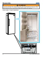
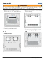
Inverter
The Compressor is operated by a Inverter
that varies the voltage to the compressor.
This is determined by the frequency input
from the low voltage board
1. To access the inverter, remove upper
air grill assembly, remove control panel
assembly (see Air Grill and Control Panel
Removal sections, Page 14).
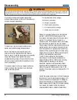
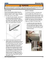
2. Remove the control box in order to gain
easy access to the door hinge area for
service. There are 4 ¼” hex screws (2
on each side) holding the control box to
the refrigerator housing. Remove these
screws.
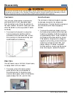
3. Unplug the 15-pin Molex power plug (A), as
well as the 2-wire converter frequency cable
(B) and the 3-wire thermistor plug (C).
Molex A
Molex
B
Molex C
Summary of Contents for Quiet Cool VCFB5301
Page 48: ...Schematic 48 2012 Viking Preferred Service 30 All Freezer Schematic Upper Section...
Page 49: ...Schematic 2012 Viking Preferred Service 49 30 All Freezer Schematic Lower Section...
Page 50: ...Schematic 50 2012 Viking Preferred Service 36 All Freezer Schematic Upper Section...
Page 51: ...Schematic 2012 Viking Preferred Service 51 36 All Freezer Schematic Lower Section...
Page 52: ...Wiring Diagrams 52 2012 Viking Preferred Service UPPER SECTION WIRING 30...
Page 53: ...Wiring Diagrams 2012 Viking Preferred Service 53 LOWER SECTION WIRING 30...
Page 54: ...Wiring Diagrams 54 2012 Viking Preferred Service UPPER SECTION WIRING 36...
Page 55: ...Wiring Diagrams 2012 Viking Preferred Service 55 LOWER SECTION WIRING 36...


