background image

13

12

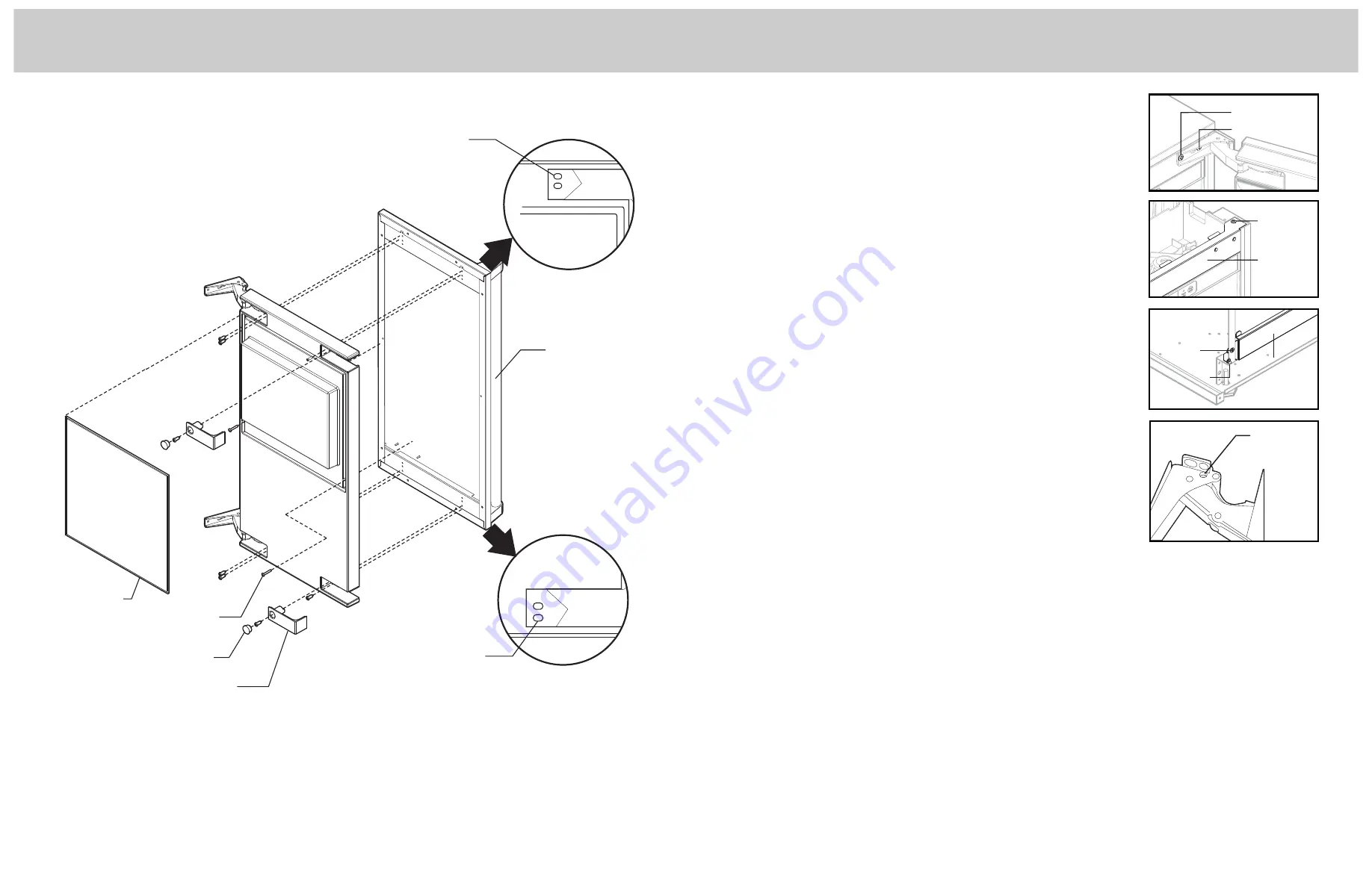
DOOR SWING CHANGE

The door can be attached to open with hinges on the left or right using new
brackets shipped loose in the ice bin. Retain all screws for re-use.

To change:
1. Remove inner screw holding each hinge to cabinet, loosen the outer screw.
2. Slide hinges to the side and remove door from cabinet. Remove outer screws

loosened in step 1 from both hinge brackets.

3. Remove two screws securing top panel to back, pull top panel back and

remove from cabinet.

4. Remove two screws at the top of the upper door hinge bracket and lift out of

the cabinet. Replace with the left hinge upper door bracket. Fasten it to the
cabinet using the original screws.

5. Return the top panel to the cabinet and fasten it with the original screws.
6. Remove kickplate and front service panel.
7. Remove two front screws and two bottom screws holding the lower door

hinge bracket to the cabinet. Replace with the left hinge lower door bracket.
Secure it using the original screws.

8. Remove the upper hinge and move it to the door's opposite side, bottom

location. Secure using the original screws.

9. Remove the original lower hinge and move it to the door's opposite side,

upper location. Secure using the original screws. 

Note: If door panel is

attached, it must be removed to access hinge screws.

10. Install a screw removed in step 2 in outer hole of upper and lower door brackets.
11. Attach the door to the cabinet using the original screws.
12. Return kickplate and front service panel to their original positions and attach to

the cabinet using the original screws.

DOOR STOP

In some situations the door can open too far and damage adjacent cabinets. To
prevent that, insert a stop into the provided hole in the top and bottom hinges

Drive the pin into the hole until the head is against the hinge.

HINGE COVERS

After the hinge pins are installed (if used) and the door panel has been attached, attach the hinge covers.
1. Slide the hinge cover over each hinge.
2. Attach the side cover over the hinge by peeling off the covering over the 

adhesive and placing it over the side of the hinge.

Note: If the hinges are used to secure the unit to the cabinet, DO NOT use the side covers.

KICKPLATE

The kickplate is black with a stainless steel covering. To use the stainless steel, no changes are required. To use the black,
remove the stainless steel covering by removing the two stainless steel screws. Replace with supplied black screws. 
DO NOT remove stainless steel covering if ice machine is used outdoors.

INSTALLATION NOTES

Built In Situations: If a finished floor is to be installed in the area after the ice machine has been built in, shims the expected
thickness of the floor should be installed under the unit to keep the machine level with the planned floor level.

Installations on a slab: Use a pump model and pump the water to the point of drainage. Pump models will pump 1 story (10
feet) high. 

Installations over a crawl space or basement: Either gravity drain or pump model units may be used, if there is not enough
room behind the machine for a drain/waste receptacle, the drain will have to be below the floor.
Note: When installed in a corner, the door swing may be limited due to handle contact with the wall or cabinet face.

Outer screw

Inner screw

Upper
door
bracket

Screw

Lower
door
bracket

Bottom
screw

Front
screw

DOOR PANEL ATTACHMENT

Gasket

Accessory
Door Panel

Cover

Machine

Screw

Use Upper

Hole at the

Top

Use Lower

Hole at the

Bottom

Hole Plug

Insert door
stop pin

Installation (con’t)

Installation (con’t)

Summary of Contents for FGNI515

Page 1: ...ront Street Greenwood Mississippi 38930 USA 662 455 1200 For product information call 1 888 845 4641 or visit our web site at vikingrange com in the US or brigade ca in Canada UL C UL Installation Guide 15 W Undercounter Freestanding Nugget Ice Machine ...

Page 2: ...nty Please observe all local and national codes and ordinances Please ensure that this product is properly grounded The installer should leave these instructions with the consumer who should retain for local inspector s use and for future reference A GFI shall be used if required by NFPA 70 National Electric Code federal state local laws or local ordinances The required use of a GFI is normally re...

Page 3: ...ance in a way that minimizes the possibility that children will find it There have been many cases in years past of children crawling inside junked and abandoned refrigeration units and becoming trapped or suffocated Contact your municipal waste disposal authority to find out the best and safest way to dispose of your old refrigeration unit 14 3 4 37 5 cm 3 7 8 9 8 cm Floor drain access hole 90 0 ...

Page 4: ...5 9 cm 22 3 4 57 8 cm 25 1 4 64 1 cm Cutout width 15 38 1 cm Cutout height 34 1 4 86 4 cm min to 35 1 4 89 5 cm max Cutout depth 24 61 0 cm Electrical requirements 115V 60 Hz 15 amp dedicated circuit 6 3 wire cord attached to product Maximum amp usage 5 0 amps Inlet water requirement 1 4 OD copper tubing inlet waterline 20 psi min to 80 psi max 50 F 10 C min to 100 F 38 C max Drain requirements 5 ...

Page 5: ...plied with ice machine 1 Remove the gasket and retain for later use 2 If the door panel is stainless steel remove any plastic covering the stainless steel panel 3 Place the panel onto the outside of the door and secure it to the door using two machine screws located at the left center and right center behind door gasket 4 Fasten the panel to the door using the 6 screws supplied with door panel In ...

Page 6: ...op of door and bottom of countertop edge from cabinet opening This is the maximum door length 5 Cut panel to width 6 Cut panel to length cabinet space kickplate space top clearance length 7 Determine top of panel 8 Mark hole locations using drawing on the back of these instructions Drawing assumes top of panel will be flush with top of door Measure hole locations from the top of the panel 9 Drill ...

Page 7: ...at insert a stop into the provided hole in the top and bottom hinges Drive the pin into the hole until the head is against the hinge HINGE COVERS After the hinge pins are installed if used and the door panel has been attached attach the hinge covers 1 Slide the hinge cover over each hinge 2 Attach the side cover over the hinge by peeling off the covering over the adhesive and placing it over the s...

Page 8: ...ION Restrictions in the drain system to the machine will cause water to back up into the ice storage bin and melt the ice Gravity drain tubing must be vented have no kinks and slope to the building drain Air gaps are typically required by local code WATER DRAIN INSTALLATION The recommended water supply tubing is 1 4 OD copper Stainless steel flex or reinforced PVC tube may also be used Install an ...

Page 9: ...REFERENCE Model and Serial number The ice machine is supplied with a power cord DO NOT remove the grounding pin from the cord s plug DO NOT use extension cords Follow all codes Connect the machine to its own 115 volt 15 amp circuit FINAL INSTALLATION 1 If the electrical outlet for the ice maker is behind the unit plug in the unit 2 Snap the black caps over the bottom of the leveling legs 3 Positio...

Page 10: ...19 18 ...

Reviews: