- 63 –
ViewSonic Corporation
Confidential - Do Not Cop
VA1721wmb
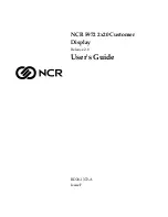
11.2 Power
Q705
NC
R714
10K 1/10W 5%
X
1uF
BL_ADJ(DC)
R706 NC
GND
R702
51R 1/10W
R721
0R05 1/10W 5%
X
R732
NC
X
+5V
+5V
PC5V
BL_ADJ
C709
0.1uF
Q701
VLCD_12V
+5V
N.C
R715
NC
on_Panel
4
BL_ON
R701
1K 1/10W 5%
VCC3.3 4
R724 NC
R731
NC
U701
NC
3
2
1
4
VI
VO
GN
D VO
VCC3.3
+12V
C720
NC
+
C705
NC
R717
10K 1/10W 5%
+5V
3,4
P.S: The 1N4148 Vf=0.7V~1V can't meet
LDO spec. The BAT42, Vf is OK but the
If=200mA(forward current) can not
meet current spec.
GND
R727
10K 1/10W 5%
47
TO-263
R720
0R05 1/10W 5%
+3V3
VCC3.3
Q701
PMBS3904
C704
NC
R705
C716
NC
VCTRL 4
Adj_BACKLIGHT
4
GND
R711
10K 1/10W 5%
on_BACKLIGHT 4
+5V
+5V
R708
10K 1/10W 5%
+
C702
4.7uF M 16V
MMBT3904
+12V
R701
+5V
1K
D704(SSM12L) Vf=0.38V and If=1A.
So when system power on, the
system loading is about 400mA
(3.3V is about 200mA and 1.8V is
about 200mA), So D35 changed
from 1N4148(or BAT42) to
SSM12L(schottky diode).
R729
NC
R710
NC
VCC1.8 4
+12V
+5V
VLCD
5
G1558-1-VS-X-3-061220
R707
U702
AIC1084-33PM
3
1
2
VIN
ADJ
VOUT
R722
NC
R704
100R 1/10W 5%
Q702
PZT2907A
H2
NC
1 2
3
4
5
6
7
8
9
1
2 34
56
7
8
9
GND
1UF
+
C707
100uF/25V
+
C712
100uF/25V
R705
47R 1/10W
+12V
R705
POWER
A
TSUM16AK-1
B
2
5
Thursday , December 21, 2006
Title
Size
Document Number
Rev
Date:
Sheet
of
C706
0.1uF
+5V
+
C703
NC
+5V
3,4
H1
NC
1
2 3
4
5
6
7
8
9
1 2 34
56
7
8
9
4.7K
Q703
PMBS3904
R707
4K7 1/10W 5%
R728
NC
H3
NC
1
2 3
4
5
6
7
8
9
1 2 34
56
7
8
9
R709
NC
X
VLCD
4.7K
VCC1.8
R725
4K7 1/10W 5%
BL_ADJ
R726 NC
+
C710
100uF/25V
P W M
+12V
4K7
+3V3
+5V
R713
NC
+5V
3,4
PC5V 3
C708
R718
NC
R712
4K7 1/10W 5%
+5V
+3V3
+5V
R723
51K 1/10W 5%
C711
0.1uF
D704
0R05 1/4W
SOT-223
0
+12V 4
C708
+3V3
Q704
AO3401
+5V
D701
LL4148
C701
NC
Q707
NC
R716
NC
VCC3.3 4
Recommond to used "Blue" parts circuit
for VCC1.8V if you want to suppoert DDC
function when system power off
+3V3
D703
NC
3
1
2
R730
NC
VLCD_12V 5
R706
D702
LL4148
+5V
C713
0.1uF
on_Panel_12V
4
For RSDS and Panel VCC=12V
0V ~ 5V
C718
0.1uF
+5V
R719
NC
1UF
0V ~ 3.3V
GND
C714
0.1uF
C708
NC
4.7K
C715
0.1uF
R703
2K 1/10W
D C
GND
CN701
CONN
2
4
6
8
10
12
1
3
5
7
9
11
Q706
PMBS3904
+
C717
10uF/16V
+
C719
NC
Summary of Contents for VA1721wmb - 17" LCD Monitor
Page 22: ...22 ViewSonic Corporation Confidential Do Not Cop VA1721wmb Block Diagram...
Page 36: ...36 ViewSonic Corporation Confidential Do Not Cop VA1721wmb...
Page 38: ...38 ViewSonic Corporation Confidential Do Not Cop VA1721wmb...
Page 41: ...41 ViewSonic Corporation Confidential Do Not Cop VA1721wmb 5 7 Packing Procedure...
Page 42: ...42 ViewSonic Corporation Confidential Do Not Cop VA1721wmb 6 Troubleshooting Flow Chart...
Page 56: ...56 ViewSonic Corporation Confidential Do Not Cop VA1721wmb Packing For Shipping...
Page 60: ...60 ViewSonic Corporation Confidential Do Not Cop VA1721wmb Picture 19...
Page 61: ...61 ViewSonic Corporation Confidential Do Not Cop VA1721wmb 10 Block Diagram...
Page 71: ...71 ViewSonic Corporation Confidential Do Not Cop VA1721wmb 12 2 MAIN BOARD PCB BUTTON VIEW...
Page 72: ...72 ViewSonic Corporation Confidential Do Not Cop VG1721wm VA1721wm 12 3 POWER PCB TOP VIEW...
Page 73: ...73 ViewSonic Corporation Confidential Do Not Cop VG1721wm VA1721wm 12 4 POWER PCB BUTTON VIEW...
Page 75: ...75 ViewSonic Corporation Confidential Do Not Cop VA1721wmb 12 7 POWER PCB TOP BUTTON VIEW Q...