background image

Antenna Installation Instructions 


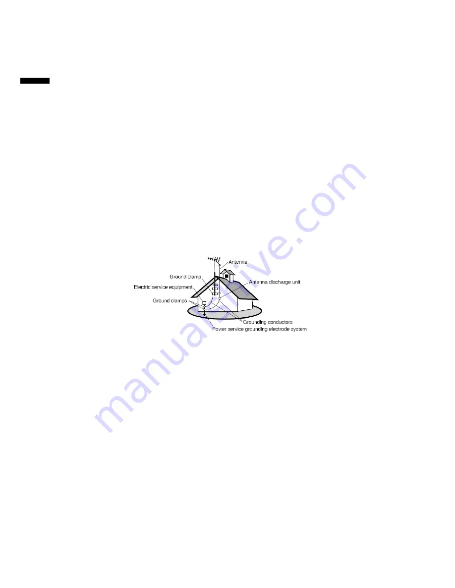
1. Outdoor Antenna Grounding 

If an outside antenna or cable system is connected to the product be sure the antenna 
or cable system is grounded so as to provide some protection against voltage surges 
and built-up static charges, Article 810 of the National Electrical Code, ANSI/NFPA 70, 
provides information with regard to proper grounding of the mast and supporting 
structure, grounding of the lead-in wire to an antenna discharge unit, connection to 
grounding electrodes, and requirements for the grounding electrode. 

2. Lightning 

For added protection for this product during a lightning storm, or when it is left 
unattended and unused for long periods of time, unplug it from the wall outlet and 
disconnect the antenna or cable system. This will prevent damage to the product due to 
lightning and power-line surges. Do not disconnect the antenna or the power cord 
during a heavy storm lighting may strike while you are holding the cable cord, causing 
serious injury; turn off your LCD TV and wait for the weather to improve. 

3. Power  Lines 

An outside antenna system should not be located in the vicinity of overhead power lines 
or other electric light or power circuits, or where it can fall into such power lines or 
circuits. When installing an outside antenna system, extreme care should be taken to 
keep from touching such power lines or circuits as contact with them might be fatal. 


Cleaning the LCD Display 


Make sure the LCD TV is turned off. 


Never spray or pour any Liquid directly onto the screen or case. 

To clean the screen: 

1.  Wipe the screen with a clean, soft, lint-free cloth. This removes dust and other 

particles.  

2.  If still not clean, apply a small amount of non-ammonia, non-alcohol based glass 

cleaner onto a clean, soft, lint-free cloth, and wipe the screen. 

To clean the case: 

1.  Use a soft, dry cloth. 
2.  If still not clean, apply a small amount of a non-ammonia, non-alcohol based, mild 

non-abrasive detergent onto a clean, soft, lint-free cloth, then wipe the surface. 

Disclaimer 

ViewSonic® does not recommend the use of any ammonia or alcohol-based cleaners on 
the LCD TV screen or case. Some chemical cleaners have been reported to damage the 
screen and/or case of the LCD TV. ViewSonic will not be liable for damage resulting from 
use of any ammonia or alcohol-based cleaners. 

ViewSonic


5

                         NX1940w/NX2240w 

E

N

G

L

IS

H

Summary of Contents for NX1940w

Page 1: ...vejledning Brukerveiledning VS11873 1E ViewSonic NX1940w NX2240w LCD TV Model No VS11871 1E User Guide Guide de l utilisateur Gu a del usuario Bedienungsanleitung Guida dell utente Anv ndarhandbok K y...

Page 2: ...enna Installation Instructions 5 Cleaning the LCD TV 5 Getting Started Package Contents 6 Preparation 7 Remote Control 9 Teletext 10 Wall Mount Bracket 11 Control Knobs 12 Preparation 13 OSD Function...

Page 3: ...3 23 EEC as amended by 93 68 EEC Art 13 with regard to Safety Following information is only for EU member states The mark shown to the right is in compliance with the Waste Electrical and Electronic E...

Page 4: ...ly at the plug and the point where if emerges from the equipment Be sure that the power outlet is located near the equipment so that it is easily accessible 11 Only use attachments accessories specifi...

Page 5: ...brominated biphenyls PBB 0 1 0 1 Polybrominated diphenyl ethers PBDE 0 1 0 1 Certain components of products as stated above are exempted under the Annex of the RoHS Directives as noted below Examples...

Page 6: ...ransmitted by any means for any purpose without prior written permission from ViewSonic Corporation Product Registration To meet your future needs and to receive any additional product information as...

Page 7: ...outside antenna system should not be located in the vicinity of overhead power lines or other electric light or power circuits or where it can fall into such power lines or circuits When installing a...

Page 8: ...box and all packaging material for future shipping needs Package Contents Remote Control AV cable For Asia use Power cord For Asia use Power cord For UK use Power cord For Pan Europe use PC Audio to...

Page 9: ...o prevent any unsafe situations no naked flame sources such as lighted candles should be placed on or in the vicinity Avoid heat direct sunlight and exposure to rain or water The equipment shall not b...

Page 10: ...AAA 1 5V 4 Power Insert the power cord in the wall socket having an AC power supply 5 Turn the TV on Press the power button of the TV to turn it on When the TV is ON the indicator turns green If the...

Page 11: ...owered off unless it is physically unplugged SOURCE Press to select input signal source 0 9 DIGIT buttons and 100 Press to enter channel numbers RECALL To display the previously selected TV channel TV...

Page 12: ...mpose the teletext over a normal broadcast picture Press again to return to Teletext mode INDEX Press INDEX to return to the main index page SUBPAGE this is subpage function REVEAL Press REVEAL to dis...

Page 13: ...asten four units M4 0 X 10mm screws to secure the wall mount bracket Note If you want to wall mount the TV for the safety of you and the appliance please use the correct hanging brackets Wall mounting...

Page 14: ...ton to change input source Power Press this button to turn on the TV or allow the TV to enter standby mode If the TV is in standby mode the indicator at the front will illuminates amber There is a wid...

Page 15: ...ns not to damage the screen 19 22 1 AV1 signal input 2 Right audio track input 3 Headphone outlet 4 TV signal input 5 SCART signal input 6 Left audio track input 7 S Video signal input 8 VGA input or...

Page 16: ...ces like a computer So you can display high definition pictures on this TV in the digital form 1 How to use HDMI 1 Connect one HDMI to the HDMI port and connect the other HDMI to device with HDMI expo...

Page 17: ...mpont Video Connections Connect the Video cable between the D Sub interface on the unit and Y Pb Pr output jacks on the DVD player Connect the Audio cable between the Audio input socket on the unit an...

Page 18: ...p When the input source is AV S VIDEO SCART YPbPr PC HDMI mode only the Sound Setup Picture Setup and Function Setup can be selected shown in the figure below When the input source is TV mode the Soun...

Page 19: ...ay adjust when necessary The following menu will appear when selecting continuously 6 Preset Designed for different types of sound output where in the voice music personal and theatre modes are preset...

Page 20: ...Temp There are four options of colour temperature provided for users normal warm cold and User You can select the three colour temperatures of normal warm and cold or manually adjust red green or blu...

Page 21: ...ext E W The user can set the teletext language 6 Reset It is used to reset the OSD settings When the input source is in AV S Video or SCART mode you can select Source OSD Language Timers TT language T...

Page 22: ...en located are stored If you would like to stop Autostore during the process simply by pressing the function button 5 Frequency show the current signal Frequency 6 AFC can be set to ON or OFF When it...

Page 23: ...obile telephone warning To avoid disturbances in picture and sound malfunctioning of your TV or even damage to the TV keep away your mobile telephone from the TV End of life directives We are paying a...

Page 24: ...Analog D Sub 15 pins separate Plug and play compatible DDC 2B Recommended Analog 1440x900 60Hz PC mode Audio input Used as a stereo earphone mini jack 3 5 Audio output L R Speaker built in 2 3 watt sp...

Page 25: ...alog D Sub 15 pins separate Plug and play compatible DDC 2B Recommended Analog 1680x1050 60Hz PC mode Audio input Used as a stereo earphone mini jack 3 5 Speaker built in 2 3 watt speakers Audio Outpu...

Page 26: ...75Hz 1440x900 VESA 800x600 60Hz 1440x900 VESA 800x600 75Hz 1440x900 MAC 832x624 75Hz 1440x900 VESA 1024x768 60Hz 1440x900 VESA 1024x768 75Hz 1440x900 1280x768 60Hz 1440x900 1280x1024 60Hz 1440x900 VES...

Page 27: ...0 VESA 1024x768 75Hz 1680x1050 1280x768 60Hz 1680x1050 1280x1024 60Hz 1680x1050 VESA 1440x900 60Hz 1680x1050 VESA 1680x1050 60Hz 1680x1050 NTSC 480I 60Hz 1680x1050 DVD 480p 60Hz 1680x1050 PAL 576I 50H...

Page 28: ...be scrambled or encoded Please contact your local cable operator Make sure that connection to other components are correct referring to the user guide Make sure that setup has been done correctly aft...

Page 29: ...leep timer set in advance Is there no signal in PC mode or HDMI mode The internal temperature of the unit has increased Remove any objects blocking the vent or clean as necessary No CATV reception or...

Page 30: ...ptions S Video Input Allows direct connection of high resolution video sources such as a Super VHS videocassette recorder Laser Disc player etc Provides improved picture resolution sharpness and clari...

Page 31: ...ewsoniceurope com 36 1814 8080 Republic of Ireland www viewsoniceurope com uk 01 411 8936 Italy www viewsoniceurope com it 02 4527 9033 Latvia www viewsoniceurope com lv 37 1706 5100 Lithuania www vie...

Page 32: ...ving service under warranty contact ViewSonic Customer Support at 800 888 8583 You will need to provide your product s serial number 2 To obtain warranted service you will be required to provide a the...

Page 33: ......

Reviews: