background image

 17


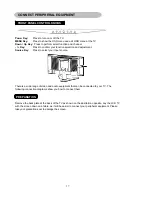
FRONT PANEL CONTROL KNOBS


Power Key:


Press to turn on or off the TV. 

MENU Key:


Press to show the OSD menu and exit OSD menu at the TV. 

Down / Up Key:

  Press to perform select function and channel.  

- / + Key:


Press to confirm your function selection and adjustment. 

Source Key:


Press to select your input source.  


There is a wide range of video and audio equipment that can be connected to your TV. The 
following connection diagrams show you how to connect them. 


PREPARATION 


Remove the back plate at the back of the TV as shown on the illustration opposite. Lay the LCD TV 
with the screen down on a table, as it will be easier to connect your peripheral equipment. Please 
take your precautions not to damage the screen. 


CONNECT PERIPHERAL EQUIPMENT 

Summary of Contents for N1750W

Page 1: ...English Français Español N1750w LCD TV User Guide ...

Page 2: ... be placed on the apparatus English Thank you very much for choosing the ViewSonic LCD TV Display We recommend that you take a few minutes to read carefully through this manual before installing and switching on the TV Please keep this manual in a safe place for your future reference TABLE OF CONTENTS INSTALLATION 2 For Your Safety 2 Product Registration 2 IMPORTANT SAFETY INSTRUCTUONS 3 Quick Ins...

Page 3: ...g the equipment off and on the user is encouraged to try to correct the interference by one or more of the following measures 1 Reorient or relocate the receiving antenna 2 Increase the separation between the equipment and receiver 3 Connect the equipment into an outlet on a circuit different from that to which the receiver is connected 4 Consult the dealer or an experienced radio TV technician fo...

Page 4: ...roduct specifications without notice Information in this document may change without notice For the most recent version of this document please check www viewsonic com No part of this document may be copied reproduced or transmitted by any means for any purpose without prior written permission from ViewSonic Corporation Product Registration To meet your future needs and to receive any additional p...

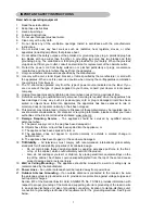
Page 5: ... normally or has been dropped 16 This product may contain lead or mercury Disposal of these materials may be regulated due to environmental considerations For disposal or recycling information please contact your local authorities or the Electronic Industries Alliance www eiae org 17 Damage Requiring Service The appliance should be serviced by qualified service personnel when A The power supply co...

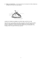
Page 6: ... AS PER NATIONAL ELECTRICAL CODE Note to the CATV system installer This reminder is provided to call the CATV system installer s attention to Article 820 40 of the NEC that provides guidelines for proper grounding and in particular specifies that the cable ground shall be connected to the grounding system of the building as close to the point of cable entry as practical ...

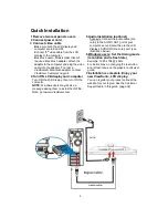
Page 7: ...urn ON the computer NOTE Windows users may receive a message asking them to install the INF file Note go to www ViewSonic com 5 Audio Installation optional Speakers Connect the audio cable line color to the AUDIO OUT port of your computer s sound card then to the LCD display s AUDIO IN line color port see illustration below 6 Windows users Set the timing mode resolution and refresh rate Example 12...

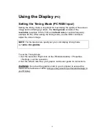
Page 8: ...ng the timing mode use the OSD controls to adjust the screen image NOTE For the best picture quality set your LCD display timing mode to 1280 x 768 60Hz To set the Timing Mode 1 Set the resolution Right click on the Windows desktop Properties Settings set the resolution 2 Set the refresh rate See your graphic card s user guide for instructions WARNING Do not set the graphics card in your computer ...

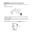
Page 9: ...flow of air Do not cover the ventilation openings on the back cover To prevent any unsafe situations no naked flame sources such as lighted candles should be placed on or in the vicinity Avoid heat direct sunlight and exposure to rain or water The equipment shall not be exposed to dripping or splashing 2 Insert the aerial plug firmly into the aerial socket ANT IN 75Ω at the back of the TV PREPARAT...

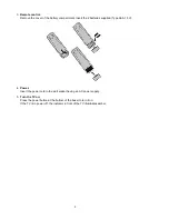
Page 10: ...the 2 batteries supplied Type AAA 1 5V 4 Power Insert the power cord in the wall socket having an AC power supply 5 Turn the TV on Press the power button at the bottom of the bezel to turn it on If the TV is in power off the indicator in front of the TV illuminates amber ...

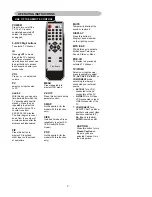
Page 11: ...V connectors of the TV S VIDEO for a S Video VCR connected to the S VIDEO connector of the TV COMPONENT for a DVD DTV Set Top Box or another component video device connected to Y Pb Pr and to the AV AUDIO inputs L and R MTS SAP Press this key to activate Multichannel Television Sound Stereo or Mono VOL Press or to adjust the volume MUTE Temporarily interrupt the sound or restore it CH Press or to ...

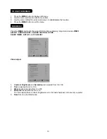
Page 12: ...button into the main OSD On Screen Display Adjust item include VIDEO ADJUST AUDIO ADJUST CLOSED CAPTION V CHIP SLEEP TIMER SET UP and PC ADJUST Video Adjust 1 Contrast Brightness and Saturation are adjusted from 0 to 100 2 Tint is adjusted from 0 to 100 3 Black Level is adjusted from 0 to 100 4 Sharpness is adjusted from 0 to 10 You can adjust picture contrast brightness color tint and sharpness t...

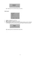
Page 13: ...s adjusted from 0 to 100 2 Bass and Treble are adjusted from 0 to 100 3 W Head Phone optional is the function for wireless headphone enable or disable You can adjust audio Volume Balance Bass and Treble to the levels you prefer When adjust any item sub OSD will show up like this ...

Page 14: ...n included Refer to your area s TV program listings for the TV channels and times of closed Caption shows The captioned programs are usually noted in the TV listings with serviceMarks such as CC Caption Mode Dialogue and descriptions for the action on the captioned TV program shows on screen Usually CH1 is the most used channel CH2 may be used for alternate languages if they are being transmitted ...

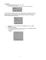
Page 15: ...roadcaster The default setting is to allow all programs to be viewed Viewing can be blocked by the type of program and by the categories chosen be blocked It is also possible to block all program viewing for a time period A There are two item could be defined One is TV Guidelines another one is Movie Guidelines B Setting up TV Guidelines Use Up Down arrow buttons to move around the matrix and pres...

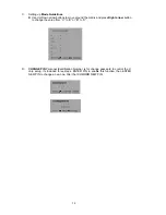
Page 16: ...d press Right arrow button to change the value from U to B or B to U D CHANGE PIN Personal Identification Number is for change password to control the V chip setup it s included three steps ENTER PIN to enable this function then ENTER NEW PIN to change a new one After that COMFIRM NEW PIN ...

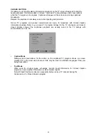
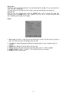
Page 17: ...rn the TV off after setting the sleep time the setting will be erased Set it again Set up 1 1 Blue screen for when no video input screen will be blue or blank If it s ON the screen will be in blue If it s OFF the screen will be blank Pre set is ON 2 Language for different language OSD MENU includes English French Spanish Pre set is English 3 AIR CATV for different TV input solution RF and cable 4 ...

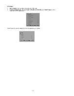
Page 18: ...o Adjust is the function auto sizing for VGA input 2 Contrast Brightness Focus Clock H Position V Position and Color Temp are the functions for PC adjustment Color Temp for you can adjust the color temperature you prefer ...

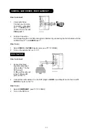
Page 19: ... Press to select your input source There is a wide range of video and audio equipment that can be connected to your TV The following connection diagrams show you how to connect them PREPARATION Remove the back plate at the back of the TV as shown on the illustration opposite Lay the LCD TV with the screen down on a table as it will be easier to connect your peripheral equipment Please take your pr...

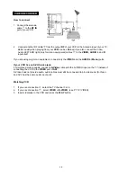
Page 20: ... AUDIO L Mono ports If your VCR has an S VHS video jack For improved picture quality connect a S Video cable with the S VIDEO input on the TV instead of connecting the VCR to the VIDEO port of AV2 S Video does not provide audio audio cables must still be connected to provide sound S Video and AV2 has the same audio input port Watching VCR 1 If you use connection select the TV channel 3 or 4 2 If y...

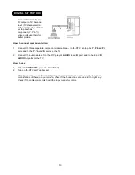
Page 21: ...e S VHS cable with the S VIDEO input and AUDIO input How to use 1 Select VIDEO or S VIDEO input source see P7 TV VIDEO 2 Turn on the external AV equipment DVD PLAYER How to connect 2 Connect the audio cables to the DVD player s AUDIO L and R ports and to the L and R AUDIO AV ports on the TV How to use 1 Select COMPONENT see P7 TV VIDEO 2 Turn on the DVD set 1 Composite Video Connect your camera ca...

Page 22: ...e TV How to use 1 Select COMPONENT see P7 TV VIDEO 2 Turn on the DTV set Top box set Warning In case you notice scrolling images wrong colors or no color no picture or even combinations of these on your screen check if the connections are done in the right way Check if the cable colors match with the Input connector colors Connect DTV set top box RF output to TV Antenna input TV channel set to CH3...

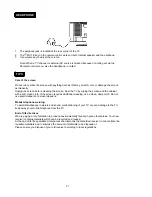
Page 23: ...the cabinet with a soft clean cloth If the screen requires additional cleaning use a clean damp cloth Do not use liquid cleaners or aerosol cleaners Mobile telephone warning To avoid disturbances in picture and sound malfunctioning of your TV or even damage to the TV keep away your mobile telephone from the TV End of life directives We are paying a lot of attention to produce environmentally frien...

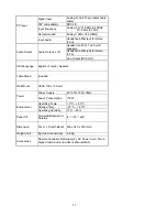
Page 24: ...m x 223mm Pixel Pitch 0 291mm x 0 291mm Display colors 16 7 million Contrast Ratio 600 1 Brightness 450cd m Viewing Angle 170 Horizontal 170 Vertical Response Time 25ms Lamp Type Life 50000 hr LCD Panel Color Temperature Cool Warm TV Tuning System NTSC 181 Channel with Electronic PLL Tuner Sound System MTS SAP Closed Caption V chip Yes TV Function Color Systems NTSC AV1 RCA x 1 Audio L R x 1 RCA x...

Page 25: ...Output Audio Output L R Line Output RCA L R OSD language English French Spanish Table Stand Included Wall Mount VESA 100 x 100 mm Power Supply AC100V 120V 60Hz Power Power Consumption 70W Operating Temp 0 C 40 C Storage Temp 25 C 60 C Environment Operating Humidity 10 85 Panel Tilt Forwards Backwards Rotation 4 18 25 Dimension W x H x D with stand 560 x 340 x 233 mm Weight net Kg w o Accessories 6...

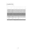
Page 26: ...80 75 37 5 75 37 5 VESA VGA 720 x 400 70 31 5 70 31 5 SVGA 800 x 600 60 37 9 60 37 9 SVGA 800 x 600 72 48 1 72 48 1 SVGA 800 x 600 75 46 9 75 46 9 VES A XGA 1024 x 768 60 48 4 60 48 4 VES AXGA 1024 x 768 75 60 0 75 60 0 MAC 16 832 x 624 74 55 49 725 MAC 19 1024 x 768 75 60 24 SVGA CVT SVGA CVT 1280x768 60 47 8 ...

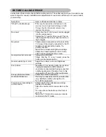
Page 27: ...rightness settings Check the Closed Captions control Some TEXT modes could block the screen Good picture but no sound Increase the VOLUME Check that the TV is not muted press the button on the remote control Good sound but poor color Adjust the contrast color and brightness settings Poor picture Sometimes poor picture quality occurs when having activated an A VHS camera or camcorder connected and ...

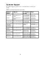
Page 28: ...urope com Europe Middle East Baltic countries and North Africa Contact your reseller service eu viewsoniceurope com Australia and New Zealand T 61 2 9906 6277 F 61 2 9906 6377 service au viewsonic com Singapore Malaysia Thailand T 65 273 4018 F 65 273 1566 service sg viewsonic com T 886 2 2246 3456 F 886 2 8242 3668 service sd viewsonic com T 886 2 2246 3456 F 886 2 8242 3668 viewsonic com www vie...

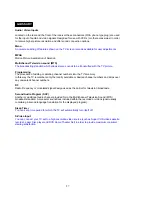
Page 29: ...rs into the TV s memory In this way the TV remembers only the locally available or desired channel numbers and skips over any unwanted channel numbers RF Radio Frequency or modulated signal design used as the carrier for television broadcasts Second Audio Program SAP Another or additional audio channel provided for in the Multichannel Television Sound MTS broadcast standard A monaural soundtrack i...

Page 30: ...eed to provide your product s serial number 2 To obtain service under warranty you will be required to provide a the original dated sales slip b your name c your address d a description of the problem and e the serial number of the product 3 Take or ship the product freight prepaid in the original container to an authorized ViewSonic service center or ViewSonic 4 For additional information or the ...

Page 31: ...tal device pursuant to part 15 of the FCC Rules These limits are designed to provide reasonable protection against harmful inter ference in a residential installation This equipment generates uses and can radiate radio frequency energy and if not installed and used in accordance with the instructions may cause harmful interference to radio communications However there is no guarantee that interfer...

Page 32: ...ViewSonic Corporation ...

Reviews: