background image

ViewSonic

 CD4620 

25 

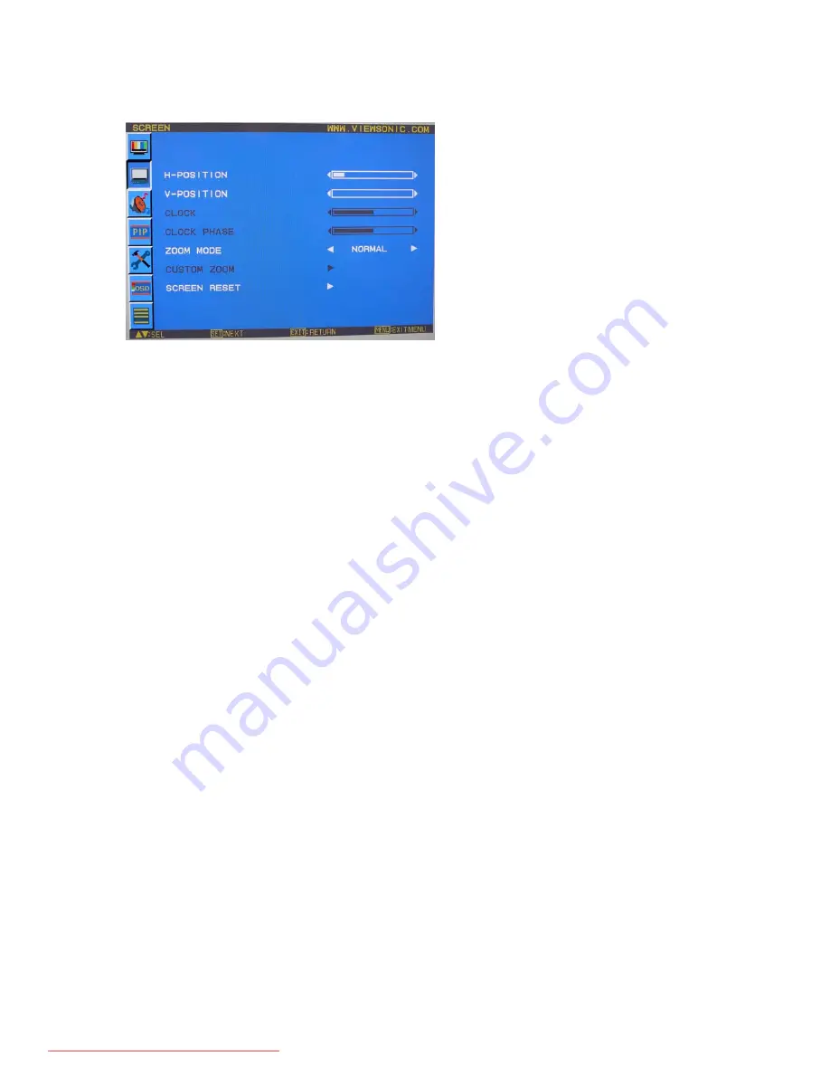
SCREEN 


H POSITION 

y

  Controls Horizontal Image position within the display area of the LCD. 

y

  Press + button to move screen to right. 

y

  Press - button to move screen to left. 


V POSITION 

y

  Controls Vertical Image position within the display area of the LCD. 

y

  Press + button to move screen to UP. 

y

  Press - button to move screen to DOWN. 

 
CLOCK 

* : INPUT RGB3,4 only


y

  Press + button to expand the width of the image on the screen the right. 

y

  Press - button to narrow the width of the image on the screen the left. 

 
CLOCK PHASE 

* : INPUT RGB3,4 only


y

  Improves focus, clarity and image stability by increasing or decreasing this setting. 


ZOOM MODE 

y

  You can select “FULL”, “NORMAL” and “CUSTOM” and “REAL”. (INPUT RGB1/2/3/4 only) You can also select “FULL”, 

“NORMAL” “DYNAMIC” and “CUSTOM” and “REAL”. (INPUT DVD/HD, VIDEO<S>, VIDEO only) 

y

  Selecting “DYNAMIC” will make the screen display panoramic with the expansion of the middle and outside of the screen 

changed. (The upper and the bottom of the image will be cut by expansion.) 

y

  Dynamic image is the same as FULL size image when HDTV signal is input. 

y

  Selecting “REAL” image will be displayed 1 by 1 pixel. 


CUSTOM ZOOM 

y

  “CUSTOM ZOOM” will be selected when you select “CUSTOM” on the screen “ZOOM” mode. 

y

  ZOOM: expands the horizontal and the vertical size simultaneously. 

y

  HZOOM: expands the horizontal size only. 

y

  VZOOM: expands the vertical size only. 

y

  H POSITION: moves to the right with + button. moves to the left with – button. 

y

  V POSITION: moves up with + button. moves down with – button. 


SCREEN RESET 

y

  Selecting Screen reset allows you to reset all OSD settings from PICTURE setting. 

y

  Select “Yes” and press “SET” button to restore the factory preset data. 

y

  Press “EXIT” button to cancel and then return to the previous menu. 

Downloaded From TV-Manual.com Manuals

Summary of Contents for CD4620 - 46" LCD Flat Panel Display

Page 1: ...for future service Warranty information contained in this User Guide will describe your limited coverage from ViewSonic Corporation which is also found on our web site at http www viewsonic com in English or in specific languages using the Regional selection box in the upper right corner of our website Antes de operar su equipo lea cuidadosamente las instrucciones en este manual Downloaded From TV...

Page 2: ...necting a Personal Computer 16 Connecting with Digital Interface Equipment 17 Connecting a DVD Player with component out 18 Connecting to a Stereo Amplifier 19 Basic Operation 20 Power ON and OFF Modes 20 Power Indicator 21 Using Power Management 21 Selecting a video source 21 Picture Size 21 Picture Mode 22 Audio Source Switching 22 Information OSD 22 OSD On Screen Display Controls 23 PICTURE 24 ...

Page 3: ...D monitor via RS 232C Remote Control 34 Appendix Installing and removing stands 35 Features 36 Troubleshooting 37 Specifications 38 Customer Support 39 Limited Warranty 40 Mexico Limited Warranty 42 Downloaded From TV Manual com Manuals ...

Page 4: ...nce could void your authority to operate the equipment For Canada This Class A digital apparatus complies with Canadian ICES 003 Cet appareil numérique de la classe A est conforme à la norme NMB 003 du Canada CE Conformity for European Countries The device complies with the requirements of the EEC directive 89 336 EEC 2004 108 EC as amended by 92 31 EEC and 93 68 EEC Art 5 with regard to Electroma...

Page 5: ...unding prong The wide blade and the third prong are provided for your safety If the plug does not fit into your outlet consult an electrician for replacement of the outlet 10 Protect the power cord from being tread upon or pinched particularly at the plug and the point where if emerges from the equipment Be sure that the power outlet is located near the equipment so that it is easily accessible 11...

Page 6: ...luorescent lamps not exceeding 5 mg per lamp and in other lamps not specifically mentioned in the Annex of RoHS Directive 2 Lead in glass of cathode ray tubes electronic components fluorescent tubes and electronic ceramic parts e g piezoelectronic devices 3 Lead in high temperature type solders i e lead based alloys containing 85 by weight or more lead 4 Lead as an allotting element in steel conta...

Page 7: ...ht to change product specifications without notice Information in this document may change without notice No part of this document may be copied reproduced or transmitted by any means for any purpose without prior written permission from ViewSonic Corporation Product Registration To meet your future needs and to receive any additional product information as it becomes available please register you...

Page 8: ...th care y Allow adequate ventilation around the monitor so that heat can properly dissipate Do not block ventilated openings or place the monitor near a radiator or other heat sources Do not put anything on top of the monitor y The power cable connector is the primary means of detaching the system from the power supply The monitor should be installed close to a power outlet which is easily accessi...

Page 9: ...nitor y Power Cord 1 8 m y Video Signal Cable 1 8 m y User s Manual in CD Wizard y Wireless Remote Control and AAA Batteries y Quick Start Guide A4 LCD monitor Quick Start Guide Video Signal Cable CD Wizard Power cored For North America Remote control AAA batteries Downloaded From TV Manual com Manuals ...

Page 10: ...own to select the adjustment with OSD menu EXIT button Activates the OSD menu when the OSD menu is turned off Acts as EXIT button to move to previous menu with OSD menu Remote control sensor and Power indicator Receives the signal from the remote control when using the wireless remote control Glows green when the LCD monitor is in active and glows red when the LCD is in POWER OFF mode When the LCD...

Page 11: ... VIDEO IN connector S VIDEO IN connector MINI DIN 4 pin To input the S video Y C separate signal EXTERNAL SPEAKER TERMINAL To output the audio signal for external speakers from AUDIO 1 2 3 jack or HDMI AC IN connector Connects with the supplied power cord RGB 1 IN HDMI 1 To input digital RGB signals from a computer This connector does not support analog input AUDIO is supported via HDMI RGB 2 IN H...

Page 12: ...ode on off DISPLAY button To switch the information OSD on off INPUT button Selects from input signal RGB1 RGB2 RGB3 DVD HD VIDEO S and VIDEO AUDIO INPUT button Press to change the audio source for each video source The audio source is changed from AUDIO1 to AUDIO2 AUDIO3 and HDMI in order Note that you cannot select the audio source for VIDEO S or VIDEO HDMI is selectable only when the video sour...

Page 13: ...istance of about 3 m 10 ft CAUTION Important the remote control system may not function when direct sunlight or strong illumination strikes the remote control sensor of the LCD monitor or when there is an object in the path Handling the remote control 7 Do not subject to strong shock 7 Do not allow water or other liquid to splash the remote control If the remote control gets wet wipe it dry immedi...

Page 14: ...V AAA batteries To install or replace batteries 1 Press and slide to open the cover 2 Align the batteries according to the and indications inside the case 3 Replace the cover CAUTION Incorrect use of batteries can result in leaks or bursting Be careful especially about the following points y Place AAA batteries matching the and signs on each battery to the and signs of the battery compartment y Do...

Page 15: ...tion under the following conditions Caution 7 Portrait position is effective only when wall mounted or ceiling mounted 7 The stands legs can not be fitted to the monitor in portrait position 7 Placing the monitor in portrait position will shorten the average life of the LCD backlight 7 Operational Environment Temperature shall be limited as shown below Temperature 5 35 C 41 95 F Operational Enviro...

Page 16: ...ting interface that comply with TÜV GS and or UL1678 standard in North America Caution For preventing the monitor from falling y Install the monitor with metal brackets for wall or ceiling installation commercially available on your own responsibility For detailed procedures of installation refer to the instructions of the metal brackets y To lessen the probability of injury and damage resulting f...

Page 17: ...ntially depends on the strength of brackets and base to which prevention device from falling is attached When you cannot ensure sufficient strength provide adequate reinforcement y Though the recommended prevention from falling is intended to lessen the probability of injury and damage it doesn t assure its effectiveness against any kind of earthquake or disaster y Do not sleep where the monitor m...

Page 18: ...urn off the power of all the attached equipment and make connections 7 Refer to the user manual included with each separate piece of equipment Wiring Diagram LCD monitor second monitor DVD HD VCR PC Equipment with Digital interface Downloaded From TV Manual com Manuals ...

Page 19: ...itor use the supplied PC Video RGB signal cable mini D sub 15 pin to mini D sub 15 pin y When connecting one or more LCD monitors use the RGB OUT connector mini D sub 15 pin y The AUDIO IN 1 2 3 or HDMI can be used for audio input For connection select AUDIO 1 2 3 or HDMI from the AUDIO INPUT button You can select HDMI only when RGB 1 or 2 is selected y The AUDIO OUT jack outputs sound from the se...

Page 20: ... y The RGB 1 RGB 2 IN connector can connect to HDMI output or DVI D output of PC y To maintain display quality use a cable with a quality prescribed by DVI standards See 29 page HDMI INPUT MODE y The AUDIO IN 1 2 3 or HDMI can be used for audio input For connection select AUDIO 1 2 3 or HDMI from the AUDIO INPUT button You can select HDMI only when RGB 1 or 2 is selected y The signal input from HD...

Page 21: ...connect the DVD HD In connector BNC on the LCD monitor use a separately available BNC connector cable You will need a BNC to RCA adapter to connect a DVD player with an RCA pin jack to the BNC connector cable not provided y The AUDIO IN 2 and 3 both RCA can be used for audio input For connection select AUDIO 1 AUDIO 2 AUDIO 3 or HDMI from the AUDIO INPUT button You can select HDMI only when RGB 1 ...

Page 22: ...nections have been made y Use an RCA cable to connect the AUDIO OUT connector RCA on the LCD monitor and the audio input on the amplifier y Do not reverse the audio left and right jacks y The AUDIO IN 2 and 3 both RCA can be used for audio input For connection select AUIDO1 AUDIO2 AUDIO3 or HDMI from the AUDIO INPUT button You can select HDMI only when RGB 1 or 2 is selected y The AUDIO OUT jack o...

Page 23: ...LCD monitor the remote control and the power button will not activate the on mode and both green and red power indicator turn off Be sure to turn the Main Power Switch to the on mode before using these two options 2 Pressing the power button NOTE Before pressing the power button be sure to turn on the Main Power button on the LCD monitor 3 Using the remote control NOTE Before operating the remote ...

Page 24: ...se the life and decrease the power consumption of the display Selecting a video source To view a video source Use the input button to set VIDEO Use the COLOR SYSTEM menu to set AUTO NTSC PAL SECAM PAL60 4 43NTSC according to your video format Picture Size RGB 1 2 3 FULL NORMAL CUSTOM REAL DVD HD VIDEO FULL NORMAL DYNAMIC REAL CUSTOM Signal Type NORMAL SIZE Recommended Size NORMAL 4 3 DYNAMIC Squee...

Page 25: ... are pressed To disable the buttons press and hold down the S and T buttons together for at least 3 seconds To enable the buttons press and hold down the S and T buttons together for at least 3 seconds again Information OSD RGB1 2 3 Video Input mode Input signal Information Audio input mode Picture Size mode DVD HD Video Input mode Audio input mode Picture Size mode VIDEO S VIDEO Video Input mode ...

Page 26: ...or control which you like Press ENTER button to decide Press MENU or EXIT button to exit Control Panel Press EXIT button to open Main menu Press S or T button to select Press INPUT button to decide Press S or T and or button to select function or control which you like Press INPUT button to decide Press EXIT button to exit OSD Screen S or T button INPUT button or button EXIT button Downloaded From...

Page 27: ...usts the noise reduction level y Press button to increase reduction level y Press button to decrease reduction level TINT INPUT RGB1 2 HDMI INPUT MODE HD DVD HD VIDEO S VIDEO only y Adjust the tint of the screen y Press button the flesh tone color becomes greenish y Press button the flesh tone color becomes purplish COLOR INPUT RGB1 2 HDMI INPUT MODE HD DVD HD VIDEO S VIDEO only y Adjust the color...

Page 28: ... HD VIDEO S VIDEO only y Selecting DYNAMIC will make the screen display panoramic with the expansion of the middle and outside of the screen changed The upper and the bottom of the image will be cut by expansion y Dynamic image is the same as FULL size image when HDTV signal is input y Selecting REAL image will be displayed 1 by 1 pixel CUSTOM ZOOM y CUSTOM ZOOM will be selected when you select CU...

Page 29: ...nd y Press button to increase TREBLE sound y Press button to decrease TREBLE sound BASS y To accentuate or reduce the low frequency sound y Press button to increase BASS sound y Press button to decrease BASS sound AUDIO RESET y Selecting Audio reset allows you to reset all OSD settings from AUDIO setting y Select YES and press SET button to restore the factory preset y Press EXIT button to cancel ...

Page 30: ...AUDIO y Selecting the sound source in PIP mode y When selecting MAIN AUDIO you will get the sound for the main picture and when selecting PIP AUDIO you will get the sound for the picture instead PIP RESET y Selecting PIP Reset allows you to reset all OSD settings from PIP setting y Select Yes and press SET button to restore the factory preset data y Press EXIT button to cancel and then return to t...

Page 31: ... directions UP DOWN RIGHT LEFT periodically Need setting the time for movement y Movement area is approximately 10mm from original position y Please locate the important information such as text within 90 area of screen image y See note 1 for this functions y PIP and STILL will be disabled when MOTION is active COLOR SYSTEM INPUT VIDEO S VIDEO only y Selecting the Color System depends on your inpu...

Page 32: ...al or source change or warning message like as no signal or out of range y A time between 1 to 10 seconds is available OFF TIMER y To select OFF TIMER mode ON OFF y In the OFF TIMER menu you can preset the monitor to automatically power down y A time between 1 to 24 hours is available y When the OFF TIMER is set the SCHEDULE settings will be disabled OSD H POSITION y Adjusts the horizontal positio...

Page 33: ...SSIVE Enable the IP function to convert interlace signal to progressive Normally use this setting y INTERLACE Disable the IP function y NOTE This mode is better suited for motion pictures but it increases chance of image retention FILM MODE INPUT DVD HD VIDEO S VIDEO only y Selects Film mode function y AUTO Enable the Film mode function This mode is better suited for movies which is converted 24 F...

Page 34: ...connected via RS 232C y ID numbers 1 to 26 are selectable DDC CI y Use to turn ON or OFF the DDC CI communication function Select ON for normal use SYNC TYPE y Select 0 3V for 0 3 Composite Sync y Select TTL for TTL Sync ADVANCED OPTION RESET y Selecting ADVANCED OPTION reset allows you to reset all OSD settings from ADVANCED OPTION settings except for DATE TIME y Select YES and press SET button t...

Page 35: ...lect which schedule to set use the up down arrows to move the number 1 to 7 of the schedule y Use the and buttons to move the cursor horizontally within the particular schedule Use the S and T buttons to increase time and select input port The SET button is used to make a selection y If you create a schedule but do not want to use a power on time select in the ON time slot y If you do not want to ...

Page 36: ...monitor you want to control using the button on the remote controller The ID of the monitor you want to control is displayed at the upper left of its screen By selecting ALL you can control all the multi connected monitors 4 Direct the remote controller at the remote control signal sensor of the PRIMARY monitor OSD appears on the monitor having the ID number you selected NOTE When the ID selection...

Page 37: ...olled by connecting a personal computer with a RS 232C terminal Functions that can be controlled by a personal computer are Connection LCD Monitor PC NOTE We have two kinds of RS 232 protocol including serious connection and no serious connection that can use by user Downloaded From TV Manual com Manuals ...

Page 38: ...l the stands so that their longer portions come to the front How to remove the stands 1 Spread the protective sheet on the fl at surface such as a desk 2 Place monitor on the protective sheet 3 Remove screws with a screwdriver and place them in a safe place for reuse Stand is not supply Stand sold as an option accessory Screws Longer portion comes to the front Stands Downloaded From TV Manual com ...

Page 39: ...s capabilities such as screen size and resolutions supported directly to your computer automatically optimizing display performance Intelligent Power Manager System Provides innovative power saving methods that allow the monitor to shift to a lower power consumption level when on but not in use saving two thirds of your monitor energy costs reducing emissions and lowering the air conditioning cost...

Page 40: ...anged the OSD Image Adjust settings may need to be re adjusted Check the monitor and your display card with respect to compatibility and recommended signal timings If your text is garbled change the video mode to non interlace and use 60 Hz refresh rate Image of component signal is greenish Check to see if the DVD HD input connector is selected LED on monitor is not lit no green or red color can b...

Page 41: ...s with 47k ohm terminated External Speaker Jack 7 W 7 W 8 ohm 9 Pin Mini D sub Resolutions Supported 640 x 480 at 60 Hz to 85 Hz 800 x 600 at 50 Hz 60Hz to 85 Hz 1024 x 768 at 50 Hz 60Hz to 85 Hz 1280 x 768 at 50 Hz 60Hz to 85 Hz 1360 x 768 at 50 Hz 60Hz to 85 Hz 1280 x 1024 at 60Hz to 85 Hz 1600 x 1200 at 60 Hz 1920 x 1080 at 60Hz Recommended Resolution NTSC PAL SECAM 4 43NTSC PAL60 Component 480...

Page 42: ...rte viewsonic com Latin America Columbia www viewsonic com la T 01800 9 156588 F 1 909 444 5655 soporte viewsonic com Latin America Mexico www viewsonic com la T 001 866 823 2004 F 1 909 444 5655 soporte viewsonic com Renta y Datos 29 SUR 721 COL LA PAZ 72160 PUEBLA PUE Tel 01 222 891 55 77 CON 10 LINEAS Electroser Av Reforma No 403Gx39 y 41 97000 Mérida Yucatán Tel 01 999 925 19 16 Other places p...

Page 43: ... to the product such as electrical power fluctuations or failure e Use of supplies or parts not meeting ViewSonic s specifications f Normal wear and tear g Any other cause which does not relate to a product defect 3 Any product exhibiting a condition commonly known as image burn in which results when a static image is displayed on the product for an extended period of time 4 Removal installation o...

Page 44: ...s warranty gives you specific legal rights and you may also have other rights which vary from state to state Some states do not allow limitations on implied warranties and or do not allow the exclusion of incidental or consequential damages so the above limitations and exclusions may not apply to you Sales outside the U S A and Canada For warranty information and service on ViewSonic products sold...

Page 45: ... to the attached Customer Support page You will need to provide your product s serial number so please record the product information in the space provided below on your purchase for your future use Please retain your receipt of proof of purchase to support your warranty claim For Your Records Product Name ________________________________ Model Number _____________________________ Document Number ...

Page 46: ... Magisterial Chihuahua Chih Tel 4136954 E Mail Cefeo soluglobales com Cuernavaca Compusupport de Cuernavaca SA de CV Francisco Leyva 178 Col Miguel Hidalgo C P 62040 Cuernavaca Morelos Tel 01 777 3180579 01 777 3124014 E Mail aquevedo compusupportcva com Distrito Federal QPLUS S A de C V Av Coyoacán 931 Col Del Valle 03100 México D F Tel 01 52 55 50 00 27 35 E Mail gacosta qplus com mx Guadalajara...

Page 47: ...ing 46 3 3 Get Function Listing 49 4 Protocol 2 without ID 51 4 1 Set function listing 51 4 2 Get Function Listing 53 4 3 Remote Control Pass through mode 55 Version control Date Reversion Changes and additions by 11 12 2007 V1 0 First release combine two protocol sets in one document Tony Kao V1 1 Remove section 3 4 Tony Kao 11 14 2007 V1 2 Update base on vender confirmation Tony Kao Jane Chen Ap...

Page 48: ...units that can sent or receive the RS232 protocol command 4 Description 4 1 Hardware specification Viewsonic LCD communication port in the rear side 1 Connector type DSUB 9 Pin Male 2 Pin Assignment Male DSUB 9Pin outside view Pin Signal Remark 1 NC 2 RXD Input to LCD Monitor 3 TXD Output from LCD Monitor 4 NC 5 GND 6 NC 7 NC 8 NC 9 NC frame GND Use of crossover null modem cable required for use w...

Page 49: ...s TV ID can use 99 to achieve and it will not have Reply command on this function Command Type Identify command type s 0x73h Set Command Command Function command code One byte ASCII code Value 1 3 Three bytes ASCII that defines the value CR 0x0D Set Function format Send Command Type s Name Length ID Command Type Command Value1 Value2 Value3 CR Byte Count 1 Byte 2 Byte 1 Byte 1 Byte 1 Byte 1 Byte 1...

Page 50: ...ness as 76 for all TV and this command is valid Send Hex Format Name Length ID Command Type Command Value1 Value2 Value3 CR Hex 0x38 0x39 0x39 0x73 0x24 0x30 0x37 0x36 0x0D No Reply CD4620 CD4220 set function table Length ID Command Command Value Range Set Function Type Code ASCII Code Hex Three ASCII bytes Comments 000 STBY Power 8 s 21 001 ON Controlled power status ON or Standby 000 VGA 001 HDM...

Page 51: ...000 POWER 001 SOURCE 002 MENU EXIT 003 UP 004 DOWN 005 LEFT 006 RIGHT Key Pad 8 s A 41 007 MUTE 000 Disable Disable RCU has no effect on HDTV 001 Enable Enabled RCU controls the HDTV This is the power up default on the HDTV Remote Control 8 s B 42 002 Pass through Pass through RCU has no effect on HDTV and all RCU command codes are transmitted to FC via the RS232 port See page 26 for more details ...

Page 52: ...r Name Length ID Command Type Command Value1 Value2 Value3 CR Byte Count 1 Byte 2 Byte 1 Byte 1 Byte 1 Byte 1 Byte 1 Byte 1 Byte Bytes order 1 2 3 4 5 6 7 8 9 If the Command is Not valid Command Type Name Length ID Command Type CR Byte Count 1 Byte 2 Byte 1 Byte 1 Byte Bytes order 1 2 3 4 5 Example1 Get Brightness from TV 05 and this command is valid The Brightness value is 67 Send Hex Format Name...

Page 53: ...mmand Response Range Get Function Code ASCII Code Hex Three ASCII bytes Comments Get Contrast 8 g a 61 000 100 Gets Contrast value Get Brightness 8 g b 62 000 100 Gets Brightness value Get Sharpness 8 g c 63 000 100 Gets Sharpness value Get Color 8 g d 64 000 100 Gets Color value Get Tint 8 g e 65 000 100 Gets Tint value Get Volume 8 g f 66 000 100 Gets Volume value 000 OFF unmuted Get Mute 8 g g ...

Page 54: ...00D Bytes order 1 2 3 4 5 6 Example Set Mute ON command ASCII Name Length Command Value1 Value2 Value3 CR Byte Count 5 6 0 0 0 00D Bytes order 1 2 3 4 5 6 Example Set Mute OFF command ASCII Name Length Command Value1 Value2 Value3 CR Byte Count 5 6 0 0 1 00D Bytes order 1 2 3 4 5 6 Example Set Tint to 50 command ASCII Name Length Command Value1 Value2 Value3 CR Byte Count 5 0 5 0 00D Bytes order 1...

Page 55: ... 5 3A 001 PIP 000 Up 001 Down 002 Left PIP position 5 3B 003 Right 000 VGA 001 HDMI1 002 HDMI2 003 AV 004 YPbPr PIP Input 5 3C 005 S Video Monitor ID 5 3D 001 026 Number 5 40 000 009 000 POWER 001 SOURCE 002 MENU EXIT 003 UP 004 DOWN 005 LEFT 006 RIGHT Key Pad 5 A 41 007 MUTE 000 Disable Disable RCU has no effect on HDTV 001 Enable Enabled RCU controls the HDTV This is the power up default on the ...

Page 56: ...n Value 1 5 for On Hours LCD Monitor will send 02Bh CR bytes to PC after receiving a valid command LCD Monitor will send 02Dh CR bytes to PC if the command is not valid The following is an example of PC requesting the volume value from the LCD Monitor PC send Get Volume value packet to Monitor In ASCII Name Length Command Value1 Value2 Value3 CR Byte Count 5 f 0 0 0 00D Bytes order 1 2 3 4 5 6 LCD...

Page 57: ...100 Gets Volume value 000 OFF unmuted Get Mute g 67 001 ON muted Gets Mute ON OFF status 000 Disable 001 Enable Get RCU h 68 002 Pass through Gets RCU mode status 000 Disable Get Key Pad i 69 001 Enable Gets Buttons ON OFF status 000 VGA 001 HDMI1 002 HDMI2 003 AV 004 YPbPr Get Input select j 6A 005 S Video Gets Input select status 000 STBY Gets the status of the HDTV power 001 ON HDTV response 00...

Page 58: ...rder 1 2 3 4 Example Remote Control pass through when Menu key is pressed 1A Name Length RCU Code1 RCU Code2 CR Byte Count 3 1 A 00D Bytes order 1 2 3 4 Example Remote Control pass through when key 1 is pressed 01 Name Length RCU Code1 RCU Code2 CR Byte Count 3 0 1 00D Bytes order 1 2 3 4 Example Remote Control pass through when OK key is pressed 1F Name Length RCU Code1 RCU Code2 CR Byte Count 3 ...

Page 59: ...Downloaded From TV Manual com Manuals ...

Reviews: