+
9LHZ
Page 3
Page 2
Fig. 2 - Indoor deployment for vertical polarisation (most smaller relay transmitters).
Fig. 3 - Wall mounted using the moulded bracket.
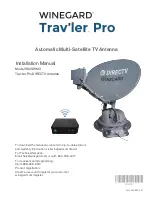
Fig. 4 - Connection diagram.
Freeview tuner
OUTPUT
VCR (optional)
ANT IN
ANT IN
ANT IN
RF OUT
RF OUT
power unit
DC power in
flylead (supplied)
Use in a loft space
For better results mount the antenna in a roof space
or similar high sheltered location
Fig. 5
. The
antenna should be mounted as high as possible and
away from metalwork such as water pipes or tanks
(cisterns), or structural steelwork. It should also be
kept as far as possible from mains wiring, although
a mains power point will be needed in reach of the
power supply lead (unless the alternative methods
of powering, described below, are employed). The
front face of the antenna should face toward the
transmitter and the polarisation must be correct.
Experiment with the mounting position before
deciding on the exact fixing position.
The support pole or mast (not supplied) can be any
suitable insulating material such as a length of
wooden dowel or plastic waste pipe. Alternatively,
the antenna can be fixed directly to a timber surface
using screws and the keyhole slots. Note that for
vertical polarisation the pole will need to be mounted horizontally.
To connect the loft-mounted antenna to your receiver you will need a length of coaxial
cable and two coaxial plugs (not supplied). The use of high-quality CAI benchmarked
cable is recommended. This may be wired via a screened wall outlet plate if desired, for a
professional-looking installation. Because of the high gain of the amplifier in the antenna,
signal loss on a long length of coaxial cable will not significantly affect the quality of the
signal delivered to the receiver.
*
Few Freeview receivers on the UK market have this capability at present, although the number
supporting it may increase in the future.
Fig. 5 - Loft mounting
Note: this diagram does
not show SCART cables.
Power supply unit
The power unit supplied is for use with standard UK (BS 1363) mains socket-outlets only.
Before connecting this equipment to the mains supply, refer to the safety instructions on
page 4.
To install, connect the lead from the power unit into the socket marked 6V 100 mA
on the back of the antenna, then plug the power unit into a suitably located mains socket
outlet and switch on.
Clearance of at least 30 mm should be allowed around the power unit for ventilation.
Do not install the power unit where it may become smothered with curtains or
other soft furnishing fabrics. When installing the power unit in a roof space ensure
that it will not come into contact with thermal insulation material.
Disconnect the power unit from the mains whenever the antenna is to remain unused for
long periods of time.
Alternative power supply
As an alternative to use of the power unit supplied, the antenna will also accept 5 6 V DC
power via the coaxial output socket. This allows it to be used with certain digital TV receivers*
which have an option to provide 5 V DC power at the antenna socket. If this method of
powering is used, the power unit supplied is not required. Consult the handbook for the
digital receiver for instructions on how to turn the antenna socket powering on.
NB Do not attempt to power this antenna using a standard 12 V masthead amplifier
power unit as this will damage the built-in amplifier.