background image


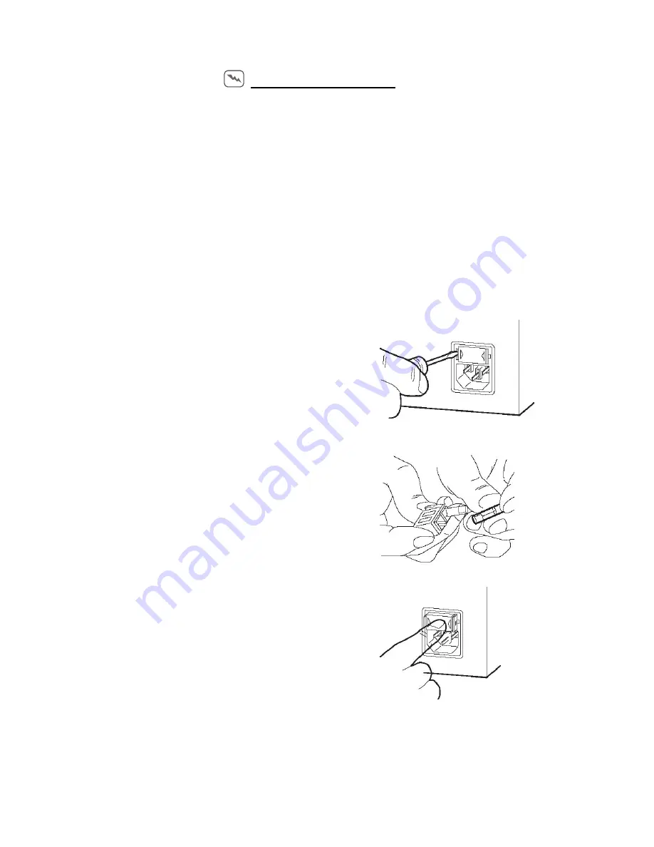
FUSE REPLACEMENT 

The power supply fuses are located at the rear of the power supply assembly.

First disconnect the mains power from your Indirect ophthalmoscope.

)

Having first disconnected your indirect ophthalmoscope from the mains power 

supply, remove the fuse holder assembly by pull out the holder or by using external 

tools.

)

Carefully withdraw the holder from the power supply.

)

A visual inspection will indicate a blow fuse, or a circuit continuity tester may be used.

)

Replace the blown fuse.

)

Replace the fuse holder.

)

Re-connect the mains power to the Indirect Ophthalmoscope, switch ON and check 

the bulb glow. 

1 Make sure that the power of the instrument is OFF 

and then unplug the power cord. 

2 Push the claws at the both ends of fuse holder with 

a slotted screwdriver and remove the fuse 

holder. 

3 Replace the fuse with a new accessory fuse. 

4. Push in the fuse holder until "click" is heard


20 

Summary of Contents for VIO-20

Page 1: ......

Page 2: ...to advise whether any repairs may be carried out by external qualified technical personnel or whether part s of the device must be returned to the manufacturer s premises for service or repairs to be...

Page 3: ...9 8 Storage Usage Period And Others 9 9 Technical Specification 10 10 Cleaning and Disinfection Information 11 11 Unpacking Installation VIO 20 12 12 Unpacking Installation VIO 30 13 13 A Dual Purpos...

Page 4: ...declared Intended for use with safer and reliable Electrical installation of the room or building in which the equipment is to be used must comply with regulations specified by the country in which t...

Page 5: ...e clear visualization of the target structures This device should be used with filters that eliminate UV radiation 400 nm and whenever possible filters that eliminate short wavelength blue light 420 n...

Page 6: ...clean Don t spill liquid into the Equipment Don t use any hazardous solvents to clean the optics and parts Only use soft dry cloth to clean the device When using the instrument after a prolonged perio...

Page 7: ...s Possible This icon denote cautions This icon represents the productive earth This icon represents Alternating current This icon represents the power switch is turned OFF This icon represents the pow...

Page 8: ...ection against Electrical shocks Class 1 Degree of protection against Electrical shocks Type B Power Requirements AC Input I P 100 230V AC 50 60Hz O P 5V DC 1A Fuses 1A Slow Blow 110V AC 500mA Slow Bl...

Page 9: ...ter b Store the instrument where air pressure temperature humidity ventilation sunlight dust salty sulfurous air etc do not give any negative side effect c Do not store or transport the instrument on...

Page 10: ...ess than 2000 mts Used less than 2000 mts Pollution Degree 2 degree 2 degree Aperture size at the Instrument 4 0mm 3 0mm 1 2mm 4 0mm 3 0mm 1 2mm Image Size at the focus Point 450mm from the Window Gla...

Page 11: ...dium Hypochlorite or 3 70 Ethanol or 4 70 Isopropyl alcohol Maintenance by user CHECKPOINTS FOR MAINTENANCE Regularly maintain and check the instrument and its parts When using the instrument after a...

Page 12: ...ndirect ophthalmoscope Ensure the intensity control in minimum position Connect the power card to the power supply Connect it to supply mains Do not position the medical equipment to make it difficult...

Page 13: ...gineers Set the sliding switch position in OFF position in indirect ophthalmoscope Ensure the sliding switch position in OFF Connect the Charger to the supply mains After charging disconnect the charg...

Page 14: ...very east adjustment of P D within 54 to 74 mm 9 It is light weight and easy to adjust 9 It has a large fin aluminium bulb holder that dissipates the heat better 9 It is very easy and quick to change...

Page 15: ...conditions with a constricted pupil In case where dilation is not advisable or possible Where a glaucoma patient is being given miotic therapy Binocular indirect ophthalmoscope affords the viewer a p...

Page 16: ...er 2 Head band 11 Teaching mirror mount 3 Front strip locking knob 12 Cover glass 4 Headband Front strip 13 Pupil adjusting lever 5 Back holder Clamp screw 14 Binocular plate 6 Filter changing lever 1...

Page 17: ...WIRELESS INDIRECT OPHTHALMOSCOPE LED Model VIO 30 Part Nomenclature Part List 19 LED Cover 22 Battery Cover 20 Battery Charger Pin 23 Battery Housing 21 ON OFF Switch 17...

Page 18: ...batteries consumed less battery thus last long and provides extra time These batteries are really safe to use x A Grade Li ion Battery x Aluminium CAN x Largest range of batteries available for almost...

Page 19: ...be in coincide Completely eliminated filament image Filament image or uneven brightness within the illuminated area has been considered an unavoidable nuisance in Binocular Indirect Ophthalmoscope Ho...

Page 20: ...the holder from the power supply A visual inspection will indicate a blow fuse or a circuit continuity tester may be used Replace the blown fuse Replace the fuse holder Re connect the mains power to...

Page 21: ...ne to Input of Power Supply Brown Wire Line Blue Wire Neutral Yellow Wire Earth All other wires color are indicated in the below Schematic diagram Ground 1A Fuse SMPS NFM 20 5 Meanwell DC Voltage Regu...

Page 22: ...owing Bulb fused 9 Change the bulb Carbon deposition in bulb contact pin 9 Remove the carbon deposit and re assemble Transformer output problem 9 Measure the output voltage of Transformer Bulb Flicker...

Page 23: ...11 2 SCHEMATIC Diagram AAIO WIRELESS Intensity Control Board Power Adopter 5V DC 1000mA Battery 3 7v DC 1000 mAh Power LED 3 4v DC 350 mA 23...

Page 24: ...Marketed by 8380 NW 64 St Miami FL 33166 USA Phone 305 406 3915 Ext 301 Fax 305 406 3917 Email javier viewlightusa com www viewlightusa com...

Reviews: