Electrical connections
18
Burner
(continued)
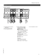
Electrical connection of two-stage or modulating burners
To control unit
To burner
2-stage or modulating module with
potential-free burner control output
Terminal codes
T6, T7, Control circuit ”two-stage
T8
burner” or ”modulation
controller” (via two-point
controller with two-stage
operation; via three-point
controller with
modulating operation)
q
Signal direction:
Control unit
→
burner
p
Signal direction:
Burner
→
control unit
The connection is made via the
extension for 2-stage/modulating
burner.
See Installation Instructions for
boiler and extension for
2-stage/modulating burner.
4.
Insert the connector
191
in the
corresponding terminal and apply
strain relief to the cable (see
“Application of Strain Relief”).
Compiled Fault Indicator Alarm
Rated voltage:
120 VAC, 60 Hz
Rated current:
3 FLA
1.
A visual and / or audible alarm
indicator can be connected.
2. Connect wires to respective
terminals on the Power Pump
Module.
5
3
0
3
2
6
9
v
1
.3
L
G
N
120 VAC Alarm Connection on
Power Pump Module
Summary of Contents for Vitotronic 300 KW3
Page 25: ...Appendix 25 5303 269 v1 3...
Page 26: ...Appendix 26 5303 269 v1 3...
Page 27: ...Appendix 27 5303 269 v1 3...

