background image

Vitosol 100-FM/200-FM  Installation, Operating and Service

5786 604 - 02 

16

Installation on Flat Roofs

or Freestanding Installation

 Overview of System Components (Model SH) 

Dimensions:

a 3” (80 mm)

b Ø 0.4” (11 mm)

c 3” (75 mm)

d 28

b

” (722 mm)

e 35

a

” (897 mm)

f 4” (100 mm)

g 2” (50 mm)

Note:

 Dimensions are rounded to the nearest 

a

” (6 mm).

Legend

A

 Collector support for angle of inclination 

 25 to 45°

B

 Collector support for angle of inclination 

 50 to 80°

1

 Collector support

2

 Base rail

3

 Adjustable support, lower part

4

 Adjustable support, upper part (2-part)

5

 Washer Ø 8.4 mm

6

 Hexagon nut M 8

7

 Hexagon bolt M 8 x 20

8

 Hexagon bolt M 8 x 25

9

 Retaining bracket

qP

 Clamping bracket

qQ

 Support brace

qW

 Mounting crossbars

qE

 Interconnection pipe

qR

 Special valve grease

Summary of Contents for Vitosol 100-FM SH1F

Page 1: ...at plate solar collectors for sloped roofs flat roofs walls and freestanding installation Product may not be exactly as shown Please file in Service Binder Read and save these instructions for future reference IMPORTANT Vitosol 100 FM Model SV1F Vitosol 200 FM Model SV2F Vitosol 100 FM Model SH1F Vitosol 200 FM Model SH2F ...

Page 2: ...of the collector installation Information contained in this and related product documentation must be read and followed Failure to do so renders warranty null and void Warranty Applicability Product documentation Licensed professional heating contractor Advice to owner Once the installation work is complete the heating contractor must familiarize the system operator ultimate owner with all equipme...

Page 3: ...n 29 Installing the General Connection Set and Collector Temperature Sensor 31 Sample System Layout 32 System Installation 33 System Fluid Calculator 34 Expansion Tank 35 System Fluid Expansion Tank Pre charge Pressure Calculator 36 Pre commissioning Checklist 37 Quick Start up 38 Set Expansion Tank Pre charge Pressure 39 Fill Flush and Leak Test the Solar Heating System 40 Vent the Solar Heating ...

Page 4: ... verified by the heating contractor These include low water cut offs flow switches if used staging controls pumps motorized valves air vents thermostats etc Repair work Repairing components which fulfil a safety function can compromise the safe operation of your heating system Replace faulty components only with original Viessmann replacement parts Ancillary components spare and wear parts Replace...

Page 5: ...escription Vitosol 100 FM Models SV1F SH1F Vitosol 200 FM Models SV2F SH2F Flat plate solar collector Absorber area 25 ft2 2 3 m2 Max stagnation temperature 293 F 145 C Max operating pressure 87 psig 6 bar Product Information Intended Use The appliance is only intended to be installed and operated in sealed pressurized systems with due attention paid to these instructions DHW tanks are only design...

Page 6: ...rm related damage The collectors should as far as possible be oriented towards the south Solar system performance drops off significantly if collectors face more than 50 off south The collectors should be mounted level or with a slight ascending slope towards the high point of the piping so that complete venting of air is assured An air vent valve c w shut off valve should be installed at the high...

Page 7: ...1 80 mm Hydronic connection accessories for multiple panel arrays qQ Interconnection pipes General Connection Set qW Connection pipe short qE Connection pipe long qR Plug qT Locking ring fitting elbow Ø 22 mm 90 qZ Profile clip qU Support sleeve qI Special grease Sensor well set qO Support sleeve wP Locking ring fitting tee Ø 22 mm wQ Sensor well wW Strain relief fitting wE Thermal insulation Coll...

Page 8: ... from inside of attic 4 Drill pilot holes into center of joist as shown Fill the pilot holes and coat the bottom of roof bracket with silicone sealant 5 Attach bracket to roof joist using the supplied 3 1 stainless steel screws qP Screws should penetrate the roof joist at least 2 64 mm Use longer field supplied screws if required to achieve necessary penetration 6 Re apply shingles if required and...

Page 9: ...019 40 1019 40 1019 40 1019 40 1019 Dimension B inches mm 42b 1077 42b 1077 42b 1077 42b 1077 42b 1077 42b 1077 Dimension C inches mm 1b 39 5 2c 68 5 3 79 3 79 3b 89 5 3b 89 5 4 100 4b 110 5 Dimension D 1 inches mm 40 1019 A 80a 2038 A A 122b 3115 A B A 165 4192 A 2xB A 207b 5269 A 3xB A 249c 6346 A 4xB A 334b 8500 A 6xB A 419b 10654 A 8xB A Dimension E inches mm 43a 1098 85b 2175 128c 3273 171a 4...

Page 10: ...53b 24220 Dimension B inches mm 88 2250 177 4500 D D 271c 6901 D E D 366a 9302 D 2xE D 460c 11703 D 3xE D 555a 14104 D 4xE D 744a 18906 D 6xE D 933b 23708 D 8xE D Dimension C 1 inches mm 3b 86 6c 172 7a 182 5 7b 193 8 203 8b 214 9a 235 10 256 Dimension D inches mm 88b 2250 88b 2250 88b 2250 88b 2250 88b 2250 88b 2250 88b 2250 88b 2250 Dimension E inches mm 94b 2401 94b 2401 94b 2401 94b 2401 94b 2...

Page 11: ...ctor C Mounting rail D Shingles E Roof joist Secure mounting brackets A on site with factory supplied screws to the roof joist For dimensions see Installing the mounting frames from pages 9 and10 Type a in mm b in mm c in mm d in mm SV 93c 2380 74c 82c 1900 2100 94b 2400 2c 70 SH 41c 1056 17c 33b 450 850 42b 1077 2c 70 Installation on Sloped Roofs ...

Page 12: ...ts are ordered separately from Viessmann B Collector C Mounting rail D Standing seam profile clamps field supplied E Support rail field supplied F Standing seam steel roof Type a in mm b in mm c in mm d in mm SV 93c 2380 74c 82c 1900 2100 94b 2400 4 103 SH 41c 1056 17c 33b 450 850 42b 1077 4 103 Installation on Sloped Roofs Install clamping brackets A to mounting rail C and secure with field suppl...

Page 13: ...necting onto the bottom of the collector IMPORTANT IMPORTANT Installing the Mounting Frames continued Installation on Sloped Roofs Installing the mounting rails Make sure the mounting rail profile is as shown The single slot in the rail must face upwards Failure to install the mounting rail correctly will not allow proper mounting plate connection 1 If more than two collectors are being installed ...

Page 14: ...rst and insert the connecting pipes qQ until they are centered between the collectors Distance between the two installed collectors should be 21 mm 6 Install all additional collectors 7 Tighten all clamping brackets 9 Remove all labels and foil cover from glass only after the system is fully operational Number of collectors 1 2 3 4 5 6 8 10 Dimension r SV collector inches mm 0 8 21 0 8 21 1 2 31 5...

Page 15: ...ase rail 3 Adjustable support lower part 4 Adjustable support upper part 2 part 5 Washer Ø 8 4 mm 6 Hexagon nut M 8 7 Hexagon bolt M 8 x 20 8 Hexagon bolt M 8 x 25 9 Retaining bracket qP Clamping bracket qQ Support brace qW Mounting crossbars qE Interconnection pipe qR Special valve grease Dimensions a 3 80 mm b Ø 0 4 11 mm c 4 100 mm d 63 1600 mm e 71 1800 mm f 4 100 mm g 2 50 mm Note Dimensions ...

Page 16: ...nsions are rounded to the nearest a 6 mm Legend A Collector support for angle of inclination 25 to 45 B Collector support for angle of inclination 50 to 80 1 Collector support 2 Base rail 3 Adjustable support lower part 4 Adjustable support upper part 2 part 5 Washer Ø 8 4 mm 6 Hexagon nut M 8 7 Hexagon bolt M 8 x 20 8 Hexagon bolt M 8 x 25 9 Retaining bracket qP Clamping bracket qQ Support brace ...

Page 17: ...tain a distance of z Example Model SV Toronto is located at approx 43 latitude 1 Determine the angle of the sun β This should be chosen so that the midday sun December 21 falls on the second row of collectors without being obstructed by shadows Solar angle 90 23 5 latitude 23 5 should be accepted as constant value for northern latitudes 90 23 5 43 23 5 2 Calculating dimension z h 2380 mm 45 23 5 z...

Page 18: ...ing on model for numbered component description 1 Secure the adjustable support lower 3 to the bottom base rail 2 with bolt 7 nut 6 and washer 5 2 Secure the upper and lower adjustable supports together with bolts 7 nuts 6 and washers 5 in accordance with the required angle of inclination Installing the Collector Supports and Adjustment Angle of Inclination ...

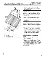
Page 19: ...et 9 and push right up to the spacer lip of the support brace qQ Installation on Flat Roofs or Freestanding Installation Note See page 15 or 16 depending on model for numbered component description Installing Freestanding Installation on Substructures CAUTION Any welds or connections to the existing substructure must be supervised by a professional structural engineer IMPORTANT X Y Collector model...

Page 20: ...eturn interconnection pipes D top and bottom into the collector headers Carefully push the collector up to the spacer lip B of the support brace qQ Visually inspect the interconnection pipes D to ensure that they are centered between the two collectors Ensure interconnection pipe is centered between collectors 10 Click clamping brackets qP into the collector edge at the top of all supports 11 Secu...

Page 21: ...racket 9 to the bottom of all collector supports do not yet tighten screws 5 Secure support braces qQ onto the retaining plates between the second and third the fourth and fifth supports etc Tighten all bolts CAUTION A structural engineer must be consulted to ensure that the existing roof structure is capable of carrying the additional weight of the collectors insert weights and support slabs Inst...

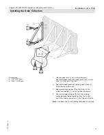
Page 22: ...description 6 Secure two mounting crossbars qW diagonally side by side to the adjustable supports respectively for between one and six collectors Only one pair of mounting crossbars are supplied for 1 to 6 collectors two pairs of mounting crossbars are supplied for 7 to 10 collectors 7 For added stability attach connecting ties to each other where they intersect using M8 or 5 16 field supplied nut...

Page 23: ...ion Lubricate all plug in joints O ring seals on the collectors Use only the special grease supplied with the connection set 10 Carefully push the next collector up to the collector that was just installed Insert the supply and return interconnection pipes D top and bottom into the collector headers Carefully push the collector up to the spacer lip B of the support brace qQ Visually inspect the in...

Page 24: ... the roof deck 3 Weights listed are the total weights of the support slabs per individual collector Model SH Secure against slipping and lifting 1 Secure against lifting only 2 Installation height above ground level ft m 26 8 26 66 8 20 66 328 20 100 26 8 26 66 8 20 66 328 20 100 Required weight at 25 3 lbs kg 712 323 1237 561 1764 800 342 155 695 315 1049 476 Required weight at 45 lbs kg 1085 492...

Page 25: ...e with circular hole 5 Gusset plate with slot 6 Washer Ø 8 4 mm 7 Hexagon nut M8 8 Hexagon bolt M8 x 20 9 Hex bolt M8 x 25 qP Retaining bracket qQ Clamping bracket qW Support brace Overview of System Components Model SH Connection pipe qE Interconnection pipe qR Special valve grease qE qR CAUTION Wall mounting hardware is only supplied for SH series collectors Wall mounting is not recommended for ...

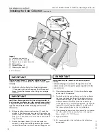
Page 26: ...h the required angle of inclination 2 Secure the adjustable support 2 to the collector support 1 with bolts 8 nuts 7 and washers 6 CAUTION Be sure to cut the adjustable supports such that approximately 11 16 17 5 mm of material is left on the end Cutting dimensions a 10c 272 mm 40 b 13d 334 mm 35 c 15c 399 mm 30 d 18f 474 mm 25 e 21b 547 mm 20 f 24b 621 mm 15 g 27e 695 mm 10 Note An uncut adjustab...

Page 27: ...the top of the wall 2 Secure the base rails with slotted gusset plate 5 at the bottom of the wall 3 Secure retaining bracket qP to the bottom of all collector supports 1 do not tighten the screws 4 Secure the support brace qW onto the retaining plates between the second and third the fourth and fifth collector supports 1 etc Tighten all bolts Dimensions a 18 481 mm b 75f 1920 mm Note Use base rail...

Page 28: ...ually inspect the interconnection pipes B to ensure that they are centered between the two collectors 10 The distance between collectors should be no greater than the width of the spacer lip C on the support brace which is 1a 32 8 mm 11 Tighten all bolts 12 Fit a snow guard on the roof above the collectors as required IMPORTANT IMPORTANT 5 Position the first collector into the retaining bracket qP...

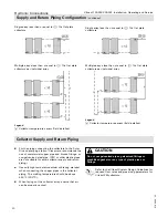
Page 29: ... Rating plate must be on the outside of the outer collectors B Collector temperature sensor location C Air vent location D Supply pipe from collector E Return pipe to collector F Alternate location for return pipe to collector CAUTION Viessmann strongly recommends not removing the cover foil from the collectors until after initial start up in order to prevent overheating CAUTION Arrows on the firs...

Page 30: ...ping Use only high temperature solder or brazing material when connecting the copper pipes in the collector piping The melting temperature should be above 450 F 232 C When laying out the collector array ensure that air can be properly vented Refer to the Vitosol System Design Guidelines for required flow rates and pipe sizing parameters for Vitosol FM collectors A Collector temperature sensor fiel...

Page 31: ...train relief fitting wQ into the sensor well 7 Insert the collector temperature sensor B supplied with solar controller until it bottoms out inside the sensor well wP and secure with strain relief fitting wQ 8 Insert the 4 long 3 Ø to 22 mm Ø adaptor qI into the compression fittings of elbow qU and tee qO and make the connection between the panel array and the supply and return piping 9 Install th...

Page 32: ...nk I Tank temperature sensor J Air separator K Solar control unit L Collector temperature sensor field installed M Fast air vent c w shutoff valve 1 P System pressure gauge R Return to collector S Supply from collector 1 Install at least one air vent valve at the highest point of the system WARNING The domestic hot water temperature must be limited to 140 F 60 C by installing a mixing device e g a...

Page 33: ...acturer must give an assurance of their adequate resistance to glycol pressure and temperature Make all connections pressure and temperature resistant observe the maximum stagnation temperature of the collector Never use Teflon inadequate glycol resistance Hemp connections insufficiently gas tight The system must be equipped with an expansion tank safety valve and circulation pump The Solar Divico...

Page 34: ...itocell 300 H EHA 119 USG 450 L x 16 00 Solar Piping select the following pipe size or combination of pipe sizes Total Length in ft Liquid Content ft in Liters Total Liquid Content in Liters b Copper x 0 05 c Copper x 0 10 1 Copper x 0 17 1a Copper x 0 26 1b Copper x 0 36 Insulated Stainless Steel Piping Kit x 0 08 Total Liquid Content of System in Liters Solar Components Solar Piping Total Liquid...

Page 35: ...from 4 to 248 F 20 to 120 C Vfv Liquid seal in the expansion tank 4 of the system volume min 0 8 USG 3 L Df Pressure factor pe 1 pe po pe Max system pressure at the safety valve in bar 90 of the safety valve response pressure po System pre charge pressure po 44 psi 0 45 psi ft static head 3 bar 0 1 bar m static head To determine the system and steam volume in the pipework the content per ft m of p...

Page 36: ...priate sizing of the expansion tank and matching of the system pressure Under cold fill conditions a minimum static fluid pressure must be maintained It can be calculated by completing the calculations in the table below IMPORTANT CAUTION The pressure relief valve must be piped to the overflow container or drain at all times since excessively hot fluid can discharge from the system CAUTION After d...

Page 37: ...ctly Have the sensors been installed correctly Have air vent valves been installed at the highest points of the system and are they open Have all bolts threaded pipe connections and covers been securely tightened Has the solar hot water tank been filled with water Does the maximum capacity of the expansion tank correspond to the value stated in the System Design Guidelines Has the gas pressure of ...

Page 38: ...flow rate see page 42 7 Provide overflow container C minimum size should equal collector fluid volume 8 Set control settings Differentials maximum tank temperature 9 Remove protective film from flat plate collectors or install the tubes Start up Legend A Solar collector B Solar Divicon pumping station C Overflow container D Expansion tank E Solar manual filling pump optional F System fill manifold...

Page 39: ... pressure of the expansion tank using the formula on page 36 4 In most cases the pre charge pressure of the diaphragm expansion tank is factory set at 44 psig 3 0 bar will be lower than the calculated charge pressure Top up with sufficient amount of nitrogen through the air valve to raise the charge pressure to equal the calculated value Legend A Heat transfer medium B Nitrogen filling C Nitrogen ...

Page 40: ...e cover foil from flat plate collectors before filling the system Cover up collectors if necessary 2 Manually open any installed isolation valves 3 Open the flow check valves on the Solar Divicon supply and return lines by Turning the combination thermometer isolation valves clockwise 45 4 Close the shut off valve G on the system fill manifold and open the drain valve H 5 The system is flushed via...

Page 41: ...ed via the air separator 3 Repeat the venting step until the float in the flow meter of Solar Divicon holds a steady position when the pump is running highest speed setting Note If air is present bubbles will be visible in the flow meter float moves 4 Adjust the flow rate via the speed selector switch of the circulation pump See page 42 for suggested flow settings for different collector arrays 5 ...

Page 42: ... 8 1 8 collectors 3 6 13 6 2 48 9 4 9 collectors 4 05 15 7 2 79 10 4 10 collectors 4 5 17 0 3 1 11 7 11 collectors 4 95 19 1 3 41 12 8 12 collectors 5 4 20 8 3 72 14 1 Check Solar Fluid Flow Rate Note Maximum of 10 Vitosol FM can be connected in one array with same side piping connections Maximum of 12 Vitosol FM can be connected in one array with opposite side connections Start up Check Switching...

Page 43: ...storage tank heat exchanger should be inspected For Vitocell 100 series tanks check and replace magnesium anode every two years Check the solar safety relief valve only if there are visible signs of it being open e g deposits drips CAUTION The building owner must notify a qualified heating contractor immediately if they notice any problems with the solar control or solar pump or a system pressure ...

Page 44: ...onnect switch and safeguard against unauthorized and or accidental reactivation IMPORTANT In areas experiencing frequent rain collector cleaning is not usually required In areas with very dry climates urban areas or dusty areas check and clean collectors periodically Use a glass cleaner or soap and water solution and rinse thoroughly with water Check Gaskets and Sealed Unions Replace all worn faul...

Page 45: ...a of the collector installation CAUTION Failure to test frost protection temperature of solar fluid can lead to freezing and damage to collector CAUTION Never mix Tyfocor HTL with water or alternate heat transfer fluid Check pH of Heat Transfer Medium The Tyfocor heat transfer medium supplied is a liquid based on 1 2 propylene glycol with a frost protection limit of 31 F 35 C Below this temperatur...

Page 46: ...Vitosol 100 FM 200 FM Installation Operating and Service 5786 604 02 46 Maintenance Record Maintenance ...

Page 47: ...with no profile clamp 0004 Pipe plug 0005 Compression connector straight 0006 Compression connector elbow 0007 Clip for assembly kit short 0008 Connection element 0009 Installation plate 0012 O ring set set of 4 0014 Profile clamp 0016 Support sleeve 22 x 1 mm set of 2 0020 Lubricant 6g Other Parts not illustrated 0125 Installation Set 0126 Copper pipe adaptor x 4 each 0127 Copper pipe Ø22 L 60mm ...

Page 48: ...Copper pipe adaptor x 4 002 Copper pipe Ø 22 l 60 mm Other Parts not illustrated 0401 Technical literature set 0402 Parts List Overview of Componentry outside of installation fittings A Vitosol FM Collector see seperate Parts List B Short connection pipe 1 For Vitosol 100 FM 200 FM C Long connection pipe 1 For Vitosol 100 FM 200 FM D Fast air vent 2 E 90 compression elbow F Sensor well set For Vit...

Page 49: ...ors Parts 003 Adaptor G female NPT male 004 Gasket 17 2 x 23 9 x 1 5 Other Parts not illustrated 0401 Technical literature set 0402 Parts List Overview of Componentry outside of installation fittings D Solar Expansion Tank K 1 NPT male to copper sweat adaptor field supplied 18L 25L 40L and 50L Tank 80L Tank Solar Expansion Tanks Additional Information ...

Page 50: ...emperature ºF ºC 293 145 293 145 Permiss operating pressure psig bar 87 6 87 6 Liquid content USG L 0 48 1 83 0 63 2 4 Weight dry lb kg 91 3 41 5 91 3 41 5 Model SV2F SH2F Gross area ft 2 m2 27 0 2 51 27 0 2 51 Absorber area ft 2 m2 25 0 2 32 25 0 2 32 Aperture area ft 2 m2 25 1 2 33 25 1 2 33 Max stagnation temperature ºF ºC 293 145 293 145 Permiss operating pressure psig bar 87 6 87 6 Liquid con...

Page 51: ...Vitosol 100 FM 200 FM Installation Operating and Service 51 5786 604 02 ...

Page 52: ...M 200 FM Installation Operating and Service 5786 604 02 Technical information subject to change without notice Printed on environmentally friendly recycled and recyclable paper Scan for digital copy of this document ...

Reviews: