background image

13

Initial start−up, inspection and maintenance

Further details regarding the individual steps 

(cont.)

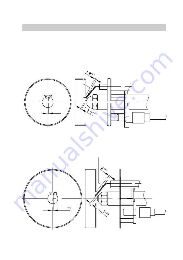
Checking and, if required, adjusting ignition electrodes

Check ignition electrodes

A

 for

wear, contamination and size (see
fig.) and replace if necessary.

5692589GB

+0.3

1.5

A

15 to 33kW

.

.

.

.

40 to 63kW

1.5

A

.

.

.

Summary of Contents for VEK

Page 1: ...eers Vitoflame 200 Pressure jet oil burner type VEK H up to 40 kW with oil preheater H from 50 kW without oil preheater for Vitorond 200 and Vitorond 222 See applicability on the last page VITOFLAME 2...

Page 2: ...oned by the system installer or a qualified person authorised by the installer Regulations Observe the following when working on this system H all legal instructions regarding the prevention of accide...

Page 3: ...close the main gas shut off valve and safeguard against unauthorised reopening Repair work Please note Repairing components which fulfil a safety function can compromise the safe operation of your he...

Page 4: ...nd maintenance 5 Further details regarding the individual steps 6 Burner control unit 17 Troubleshooting Diagnosis burner control unit LMO 14 20 Component summary 26 Connection and wiring diagram 28 P...

Page 5: ...wn I M 7 Checking tightness of electrical connections M 8 Cleaning burner 11 I M 9 Checking impeller fixings I M 10 Checking flame tube fixings M 11 Nozzle replacement 12 I M 12 Checking and if requir...

Page 6: ...200 oil burner features very good combustion values which are achieved without the use of fuel oil additives combustion improvers We do not therefore recommend the use of such combustion improvers 1 C...

Page 7: ...This allows the oil to drain from the oil pump 4 Insert a pressure gauge range 0 25 bar and a vacuum gauge range 0 1 bar Note Seal the pressure and vacuum gauges only with copper or aluminium gaskets...

Page 8: ...ure rises Anti clockwise pressure falls Note For standard values for burner adjustment see page 36 8 Check the actual emission values after adjusting the oil pressure 9 Isolate the mains electricity s...

Page 9: ...Blast tube connection set screw B Test nipple C Air damper D Blast tube connection E Clamping screw F Sensor plate G Flame tube Note Do not release clamping screw E otherwise the 0 point setting of t...

Page 10: ...t Operating and service instructions 1 Complete and detach the customer registration card H Give the system user this part for safe keeping H Retain the heating engineer part 2 Keep all parts lists op...

Page 11: ...ividual steps cont Cleaning the burner 1 Set burner to maintenance 2 Clean the housing the flame tube sensor plate A ignition electrodes B flame monitor C and impeller D For cleaning the combustion ch...

Page 12: ...holding the blast tube connection Note For make and type of nozzle see standard values for burner adjustment on page 36 7 Only for 15 to 33 kW Check seal washer B on deflector E of the sensor plate an...

Page 13: ...rther details regarding the individual steps cont Checking and if required adjusting ignition electrodes Check ignition electrodes A for wear contamination and size see fig and replace if necessary 56...

Page 14: ...r Fault shutdown at the end of the safety period Burner start with flame monitor lit from an outside source Fault shutdown after max 40 s 3 Push flame monitor A into flange C until strap B audibly cli...

Page 15: ...d with the standard burner adjustment values see page 36 1 Fit the burner lid on the burner housing 2 Set the scale for blast tube connection adjustment with blast tube connection adjusting screw A to...

Page 16: ...ndividual steps cont Cleaning and if required replacing the oil pump filter Danfoss oil pump type BFP 31 A Filter plug B O ring replace C Filter replace Suntec oil pump type ALE 35 A Filter clean or r...

Page 17: ...Burner motor K Oil preheater Burner control unit LOA 14 tw Oil preheat time up to 12 min 1 t1 Pre purge time approx 13 s t2 Safety time max 10 s t3 Pre ignition time approx 13 s t3n Post ignition tim...

Page 18: ...Burner control unit LMO 14 Program sequence see page 17 Sensor current H min requirement 40 mA H max permiss without flame 5 5 mA Undervoltage The burner control unit initiates a safety shutdown if th...

Page 19: ...shutdown After a fault shutdown the burner control unit remains locked out non modifiable fault shutdown and the red lamp lights up This state is also maintained after the mains power supply has faile...

Page 20: ...s the type of fault For explanations see the table on page 22 3 To reset the burner and exit the fault display press the reset button approx 1 s less than 3 s Colour of the LEDs Operating condition Co...

Page 21: ...s LED on burner control unit illuminates red Correct the fault Connect interface see interface op erating instructions Call up data transfer via interface accessory H Hold in reset button approx 5 s u...

Page 22: ...nnection If phases are correctly connected replace burner control unit Burner does 2 Motor faulty Replace motor not start with fault 2 Clutch between motor and oil pump faulty Replace clutch 2 Oil pum...

Page 23: ...hanged Connect correctly acc to instructions on pump 2 Vacuum in suction line too high higher than 0 35 bar Check size of oil pipe cross section Replace filter Check external fuel oil valve 2 External...

Page 24: ...line Seal line and filter extinguishes during 7 Nozzle faulty Nozzle replacement during operation 7 Burner incorrectly adjusted Adjust pre settings correctly see page 36 7 Sensor plate contaminated Cl...

Page 25: ...flame tube extension or combustion chamber liner Incorrect 0 point adjustment of blast tube connection Check and if necessary correct blast tube connection 0 point adjustment see page 15 CO2 content...

Page 26: ...valve B Burner control unit C Reset button with extension D Connection panel E Return line F Suction line G Fan motor H Oil pump K Solenoid valve L Blast tube connection setting screw M Oil supply lin...

Page 27: ...valve M Oil supply line N HF ignition unit O Ignition cable P Ignition electrodes R Flame tube S Flame tube extension only for 15 to 33 kW T Sensor plate U Oil burner nozzle V Flame monitor W Blast tu...

Page 28: ...28 Connection and wiring diagrams Connection and wiring diagram 5692 589 GB N L K H G F E D C B A M 1 1 1 1 3 4 1 2 1 1 ON 6 3A slow...

Page 29: ...cessories via system plug in connector fA e g Vitoair extension lead etc 2Connection of external safety equipment via system plug in connector aB 3Connection of external controlled switch OFF via syst...

Page 30: ...41 Solenoid valve coil for Danfoss oil pump 042 Ignition cables set 043 Flame monitor QRB 049 Burner hood latches 080 Small parts comprising 80a Plug spigot hexagon socket 4 mm 80b Plug spigot compres...

Page 31: ...31 Parts list Parts list cont 5692 589 GB 002 001 017 005 049 009...

Page 32: ...32 Parts list Parts list cont 5692 589 GB 80k 80e 80r 80f 80e 008 007 013 018 004 A 014 80i 80h 011 012 006 024 028 80g 80a 80b 80c...

Page 33: ...33 Parts list Parts list cont 5692 589 GB 047 020 041 021 040 80o 80p 034 033 046 039 038...

Page 34: ...34 Parts list Parts list cont 5692 589 GB 030 80d 80l 044 042 045 80m 032 027 80d 019 043 023 022...

Page 35: ...hput l h 45 Connections R fem thread e Suction and return lines of the oil hoses supplied Rated output kW 33 40 50 63 Burner type VEKI 1 VEKI 2 VEKII 1 VEKII 2 Type test no to EN 267 5G971 2001S 5G972...

Page 36: ...baffle Number of plugs remaining in the baffle mbar 0 0 0 0 Rated output kW 33 40 50 63 Oil burner nozzle 1 Make Fluidics Make Danfoss Type Type Gph 60 SR 0 85 45 SF 1 00 60 B 1 00 80 H 1 50 Oil press...

Page 37: ...37 Appendix 5692 589 GB...

Page 38: ...bar Vacuum actual bar after maintenance bar Soot indicator located after maintenance Carbon dioxide content CO2 actual by vol set by vol Oxygen content O2 actual by vol set by vol Gross flue gas tempe...

Page 39: ...39 Appendix Maint service Maint service Maint service Maint service 5692 589 GB...

Page 40: ...bar Vacuum actual bar after maintenance bar Soot indicator located after maintenance Carbon dioxide content CO2 actual by vol set by vol Oxygen content O2 actual by vol set by vol Gross flue gas temp...

Page 41: ...41 Appendix Maint service Maint service Maint service Maint service 5692 589 GB...

Page 42: ...42 Appendix 5692 589 GB...

Page 43: ...nit 17 Flame monitor checking 14 I Ignition electrodes checking 13 Ignition electrodes setting 13 N Nozzle replacement 12 O Oil pressure adjustment 7 Oil pump filter cleaning and if required replacing...

Page 44: ...1952 675000 Fax 44 1952 675040 E mail info uk viessmann com 44 Applicability from serial no 7185410 5 00001 kkk 7185411 5 00001 kkk 7185412 5 00001 kkk 7185413 5 00001 kkk 7185414 5 00001 kkk 7185415...

Reviews: