10
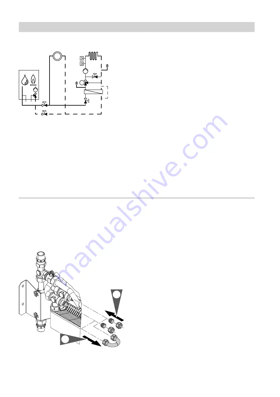
System scheme with sub-mounting kit
M
A
B
H
G
F
E
C
D
K
Fig. 8
A
Heating circuit without mixer
B
Heating circuit with mixer (underfloor heating cir-
cuit)
C
Bypass
D
Volume balancing line
E
Plate heat exchanger for system separation
F
3-way mixer
G
Heating circuit pump
H
Flow temperature sensor
K
Temperature limiter to restrict the maximum tem-
perature of underfloor heating systems
Information regarding the heating circuit with
mixer
Install a drain & fill valve on site, in the flow of the heat-
ing circuit with mixer. This is required during commis-
sioning for filling and venting the heating circuit.
The expansion vessel integrated into the boiler can
also be used for the heating circuit with mixer.
Check whether the size of the integral expansion ves-
sel is adequate for the connected heating circuits.
Information on the underfloor heating circuit
Fit maximum temperature limiter
K
to the heating flow
line at least 1 m downstream of the circulation pump.
Connecting heating circuits with permeable pipework
When connecting heating systems with permeable
pipework (DIN 4726), seal off the volume balancing
line between the two heating circuits.
Note
If the volume balancing line has been removed, install
a separate expansion vessel in the regulated heating
circuit.
Removing the volume balancing line
2.
1.
Fig. 9
1.
Undo the union nuts and remove the balancing line
and locking rings.
2.
Seal the connections with the plugs and union nuts
supplied.
Lubricate the O-rings with the valve grease sup-
plied.
Connecting the heating circuits
(cont.)
5785 284 GB
Summary of Contents for Sub Mounting Kit
Page 15: ...15 5785 284 GB ...


