3
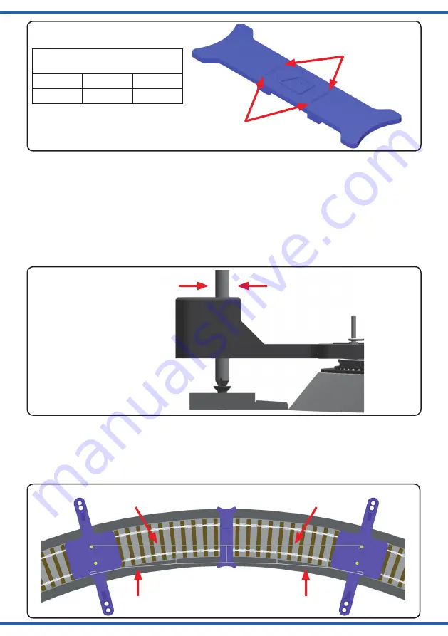
Fig. 2
Abb. 2
marks for the max.
deviation of the
running wire
Markierungen für maximale
Fahrdrahtabweichung
4. Anwendung
Setzen Sie eine der beiden Mastpositionslehren
auf das Gleis auf und fixieren Sie diese mit einem
der beiligenden Befestigungsstifte oder dem
Spezialschraubendreher Art.-Nr. 4199 an der
Position des bereits montierten Mastes. Stecken
Sie dazu den Stift bzw. den Schraubendreher
durch die entsprechende Bohrung der Lehre bis
auf die bereits vorhandene Befestigungsschraube
des ersten Mastes (siehe Abb. 3).
4. Using
Place the mastposition gauge on the track and fix
it at the position of the first mast with one of the
enclosed tacks or with the screwdriver item-No.
4199. For that, please put the tack or the screw
-
driver through one of the holes of the gauge, down
to the fixing-screw of the first mast (see fig. 3).
Fig. 3
Abb. 3
Befestigungsstift
fixing-tack
Setzen Sie nun die Fahrdrahtabweichungslehre
sowie die zweite Mastpositionslehre auf das Gleis
auf und hängen Sie den ausgewählten Fahrdraht
in die beiden Lehren ein (siehe Abb. 4). Achten
Sie darauf, dass die Ösen richtig in die Fahrdraht-
aufnahmen eingehängt sind.
Now place the running wire deviation gauge and
the second mastposition gauge on the track and
fix the running wire between both gauges (see
fig. 4). Please check, that the eyelet is correctly
fixed on the running wire fastening.
Fig. 4
Abb. 4
Fahrdraht
running wire
Tragseil
bearing rope
Maximale Fahrdrahtabweichung
Max. deviation of the running wire
H0
TT
N
6,5 mm
4,5 mm
3,5 mm


