


U S E R ‘ S M A N U A L
|
V I B A L A N C E 2 . 0 | 19
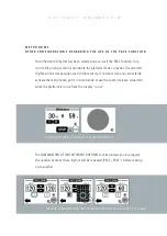
If so desired, the control tower may be moved, separating it from the sliding
platform, thanks to the extendable spiral cable
(Figure 7)
. To do so, slide or sli-
ghtly lift the tower, do not place it upon the safety connector. To avoid elevated
tension in the connector, avoid extending the spiral cable to its full limit.
To transport
Vibalance 2,0
with maximum safety, disconnect the connector, first
unscrewing the safety connector, so that it then may be removed.
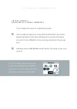
M O B I L I T Y O F T H E C O N T R O L T O W E R
M A X I M U M W E I G H T
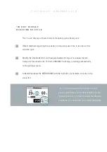
D E S C R I P T I O N O F T H E F U N C T I O N I N G O F T H E C O N T R O L T O W E R
T O U C H D I S P L A Y
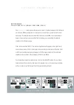
The maximum load for the vibratory platform should not exceed 200 kg. In order
to avoid lifting the platform off of the floor or moving about, do not submit the
vibratory plate anchors to loads exceeding 40 kg.
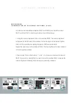
The
Vibalance 2.0
control tower allows you to select the vibration amplitude,
vibration frequency, vibration frequency cycles, ignition timing, and rhythm
feedback, all using the touch display.
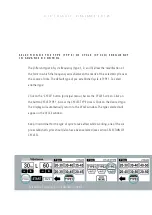
Once one is sure that both the platform’s L-shaped connector and the power
cable are properly connected, activate the principal on switch at the base of the
control tower. You should see that:


