


VIBRODIAG
www.viditech.eu
sales
@viditech.cz
11
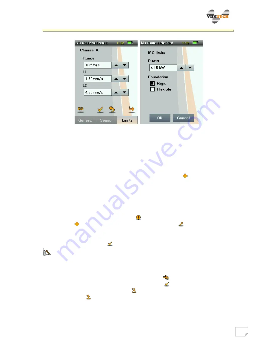
Fig. 8 Limits setup for channel A and B.
6
Database, routes
Main menu
Database, routes
6.1
Measuring places
The instrument requires the following to be defined in order: Factory – Building –
Machine – Place. Entering a new item is done by tapping on
, deleting an item by
selecting the cross icon. The structure of the defined place can be browsed using arrows.
Using the arrow, in the bottom right corner at any time, it is possible to return to the
Database, routes item.
While defining a machine, individual descriptions and parameters are selected: Machine
title, Type, Power, and additional. After successfully defining a machine a preview of the
selected parameters is displayed under the icon (fig. 9). Followed by place definition of
Machine using
icon, and place parameters setup, using icon
, with switching screens
left/right, see fig. 10. Here it is possible to set parameters of channel A and B and
predefined options of section Measuring – Route measuring. All performed changes need
to be finally approved by the
symbol. Displaying measured data is possible using the
icon, with subsequent data type selection.
6.2
Routes
After setting measuring places, it is necessary to move to the item Routes, here it is
possible to create a new route and enter it using the
symbol. To add places to the
route, the process is as follows: activate the route using , open Measuring places, in the
top right corner of the screen the symbol appears (Fig. 11b). By gradual place selection
and tapping on the symbol, the place is added to the activated route (Place added!).
Places are displayed in the activated route in fig. 11c, and it is possible to move them
freely among each other.