background image

Installation

Vidikron Vision Model 110 Installation/Operation Manual

23 

PRE

L

IMINAR

Y

Installing the AutoScope Lens 
Motor (Vision 110/CineWide 
with AutoScope)

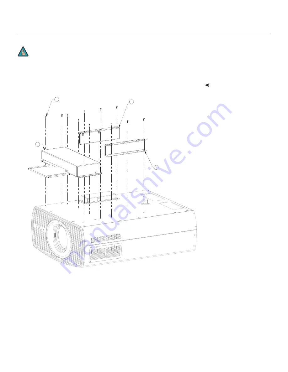
Figure 3-6 shows the Vision 110/CineWide with AutoScope motor assembly.

Figure 3-6. Vision 110/CineWide with AutoScope Motor Assembly - Exploded View

1. Do not install the CineWide lens yet, only the fixed CineWide base plate 

or AutoScope lens motor. You will install the CineWide lens after you 
install the projector and adjust the primary lens. 

2. Some components shipped with your projector may differ slightly from 

what is shown in these instructions. 

Note

3

4

Screw, Phillips Pan-Head,
M6-1.0 x 12mm (14x)

1

AutoScope 

Lens

Motor

2

CineWide with AutoScope
Ceiling Mt. Adapter/
Projector Stand, Right

CineWide with AutoScope
Ceiling Mt. Adapter/
Projector Stand, Left

Summary of Contents for Vision 110

Page 1: ...1080p Digital Light Processing DLP Projector Vision 110 Vision 110 CineWide Vision 110 CineWide with AutoScope 110 VERSION 1 1 I N S T A L L A T I O N O P E R A T I O N M A N U A L...

Page 2: ......

Page 3: ...cover normal maintenance This Limited Warranty does not cover cabinets or any appearance items failure resulting from accident misuse abuse neglect mishandling misapplication faulty or improper insta...

Page 4: ...repair These arrangements must be made through the selling Vidikron Dealer If this is not possible contact Vidikron directly for a Return Authorization number and shipping instructions Vidikron will...

Page 5: ...___ ________________________________________ Model Purchased Date ____________________________________________________________________________________________________________ Serial Number ___________...

Page 6: ...th the apparatus When a cart is used use caution when moving the cart apparatus to avoid injury from tip over 13 Unplug this apparatus during lightning storms or when unused for long periods of time 1...

Page 7: ...urge immunity test EN 61000 4 6 Electromagnetic compatibility EMC Part 4 Testing and measurement techniques Section 6 Conducted disturbances induced by radio frequency fields immunity test EN 61000 4...

Page 8: ...S 003 Cet appareil num rique de la classe B est conforme la norme NMB 003 du Canada Lamp s inside this product contain mercury This product may contain other electronic waste that can be hazardous if...

Page 9: ...tures and Benefits 3 Key Features and Benefits 3 Parts List 4 2 Controls and Functions 5 Vision 110 at a Glance 5 Vision 110 Rear Panel 6 Vision 110 Rear Connector Panel 8 Vision 110 Remote Control 10...

Page 10: ...troller Connection 34 Connecting 12 volt Trigger Outputs to External Equipment 35 Connecting an External IR Receiver to the Vision 110 36 Connecting to AC Power 36 Turning on the Power 37 Adjusting th...

Page 11: ...Y 5 Maintenance and Troubleshooting 59 Lamp Replacement 59 Filter Replacement 60 Troubleshooting Tips 61 6 Serial Communications 63 RS 232 Connection and Port Configuration 63 Serial Command Syntax 6...

Page 12: ...Table of Contents xii Vidikron Vision Model 110 Installation Operation Manual P R E L I M I N A R Y Notes...

Page 13: ...7 3 10 HDMI Source Connections 29 3 11 Digital DTV RGB or Component Video Connections HD1 HD2 30 3 12 Digital DTV RGB or Component Video Connections HD3 31 3 13 Analog RGB Connections 32 3 14 S Video...

Page 14: ...List of Figures xiv Vidikron Vision Model 110 Installation Operation Manual P R E L I M I N A R Y Notes...

Page 15: ...our comments about this manual Send them to info Vidikron com Textual and Graphic Conventions Text Conventions The following conventions are used in this manual in order to clarify the information and...

Page 16: ...ortance or special significance They also provide supplemental information CAUTIONS alert users that a given action or omitted action can degrade performance or cause a malfunction WARNINGS appear whe...

Page 17: ...re digital connections from input to light engine for absolutely stellar pictures In addition Vidikron s multiple aspect ratio control includes its unique IntelliWide mode for viewing standard video f...

Page 18: ...r Service at 888 4VIDIKRON Vision Model 110 DLP Projector Remote Control Unit and two 2 AAA size batteries AC Power Cord Warranty information and registration card Vidikron Vision Model 110 Installati...

Page 19: ...0 components Figure 2 1 Vision 110 Front Bottom Side View 1 PRIMARY PROJECTION LENS 2 VIDIKRON LOGO The logo can be rotated to match the projector orientation inverted ceiling mounted or upright To ro...

Page 20: ...ppears here indicating the cause 3 RUN LED Lights blue to indicate that the projector is functioning normally Flashes blue one second on one second off to indicate an error condition Flashes blue one...

Page 21: ...e the menu cursor right in the OSD When no menu is present on screen the RIGHT button toggles through the different sources in this order Composite VID S Video HD 1 RCA HD 2 BNC HD 3 VGA Y Pb Pr HDMI...

Page 22: ...om an external remote control or infrared receiver It is a 3 5 mm mini phono jack wired as follows Ring 5V Tip IR Input TTL level Sleeve Ground 5 RS 232 485 CONTROL PORT A male 9 pin D sub connector f...

Page 23: ...VI or HDMI output 8 HD3 INPUT Provides a standard 15 pin VGA style connection to either an RGB or component high definition source or to a personal computer The Vision 110 automatically detects the in...

Page 24: ...emote control and the paragraphs that follow describe its functionality Figure 2 4 Vision 110 Remote Control FOCUS LENS ZOOM LIGHT OFF ON VID S VID HDMI1 HD2 SOURCE PICTURE MEMORY ASPECT RATIO HD1 INF...

Page 25: ...e source 4 INFO Press to display input signal and product information Cursor Keys Use these buttons to select items or settings adjust settings or switch display patterns EXIT Press to save menu item...

Page 26: ...f the screen LBOX Letterbox For viewing LaserDisc movies or non anamorphic DVDs on a 16 9 screen IWIDE IntelliWide Enlarges a 4 3 image horizontally in a NON linear fashion to fit 16 9 full screen dis...

Page 27: ...will not use the remote control for a long time remove the batteries to avoid damage from battery leakage Notes on Remote Control Operation Make sure that there is nothing obstructing the infrared bea...

Page 28: ...otor 22 3 Mount the projector 28 4 Connect signal sources to the projector 29 5 Connect external controller to RS 232 port optional 34 6 Connect 12 volt trigger outputs to AutoScope lens motor and or...

Page 29: ...d less vibrant Table 3 2 Projector Installation Options Advantages Considerations Front Screen Floor Mount Installation Easy to set up Can be moved or changed quickly Easy to access Shares floor space...

Page 30: ...nce Table 3 3 lists the available lens options for the Vision 110 and their associated throw ratios Table 3 3 Vision 110 Lens Options and Throw Ratios Lens Option Note 2 Throw Ratio with Primary Lens...

Page 31: ...he projector and screen as shown in Figure 3 2 you can use the lens shift controls to center the image on the screen Lens shift is generally expressed as a percentage of the screen height or width as...

Page 32: ...I N A R Y Figure 3 4 Horizontal Lens Shift EXAMPLE ONLY 0 Screen Center 100 Width Lens Shift 1 0 x W 50 Width Lens Shift 0 5 x W Screen Width W Note This is a general example of lens shift Lenses vary...

Page 33: ...ts Lens Option A1 A2 B C D E Lens Shift Limits as Percentages of Screen Height or Width Notes 1 and 2 Vertical Note 2 Up 10 31 30 32 28 30 Down 10 71 61 62 65 63 Horizontal Note 2 Left 5 17 12 Right 5...

Page 34: ...ture may cause drifts in the projector circuitry which may affect performance Keep the projector away from devices that radiate electromagnetic energy such as motors and transformers Common sources of...

Page 35: ...the right side of the Lens Cavity Carefully insert the back of the lens assembly into the hole in the lens flange Gently push the lens assembly in until it is seated flush against the flange and the...

Page 36: ...he Projector Front Jewelry Tighten the hex screws at the top and bottom of the jewelry to secure it 3 5 Installing the Optional CineWide Lens Mount If you are installing a standard non CineWide Vision...

Page 37: ...w 1 Do not install the CineWide lens yet only the fixed CineWide base plate or AutoScope lens motor You will install the CineWide lens after you install the projector and adjust the primary lens 2 Som...

Page 38: ...e adapters bring the attachment points for the projector mounting rails included with the projector ceiling mount kit from the bottom of the projector up and around the AutoScope lens motor housing Fo...

Page 39: ...Installation Vidikron Vision Model 110 Installation Operation Manual 25 P R E L I M I N A R Y Figure 3 7 Vision 110 with Ceiling Mount Adapters Projector Stands DO NOT OVER TIGHTEN THE SCREWS Caution...

Page 40: ...own in Figure 3 8 Line up the mounting holes on the lens motor housing with those on the underside of the projector Secure the motor to the projector with the eight 8 remaining M6 x 12mm Pan Head Phil...

Page 41: ...Wide 1 Place the projector upside down on a blanket or other soft surface 2 Line up the mounting holes on the lens mount base plate with those on the bottom of the projector directly below the primary...

Page 42: ...u can invert the Vision 110 and suspend it from the ceiling using a specially designed ceiling mount fixture The projector can also be inverted and placed in an enclosure above and behind the viewing...

Page 43: ...the connector panel press the door release button so it pops out Turn the knob clockwise or counter clockwise and pull gently on it to open the door Connecting Source Components to the Vision 110 Conn...

Page 44: ...s See Figure 3 11 and Figure 3 12 Figure 3 11 Digital DTV RGB or Component Video Connections HD1 HD2 WIRED REMO RED REMOTE HD2 BNC HD1 RCA HD1 RCA HD2 BNC HD3 VGA Y Pb Pr HD3 VGA Y Pb Pr Vert Horiz Re...

Page 45: ...el 110 Installation Operation Manual 31 P R E L I M I N A R Y Figure 3 12 Digital DTV RGB or Component Video Connections HD3 HD3 VGA Y Pb Pr HD3 VGA Y Pb Pr Green Y Blue Pb Red Pr Horiz Vert DTV or Pr...

Page 46: ...110 Installation Operation Manual P R E L I M I N A R Y Analog Computer RGB Connections See Figure 3 13 Figure 3 13 Analog RGB Connections HD2 BNC HD2 BNC HD3 VGA Y Pb Pr HD3 VGA Y Pb Pr Vert Horiz Re...

Page 47: ...Installation Operation Manual 33 P R E L I M I N A R Y S Video Composite Video Connections See Figure 3 14 Figure 3 14 S Video and Composite Video Connections HD3 VGA Y Pb Pr HD3 VGA Y Pb Pr DVD Playe...

Page 48: ...omation system if present to the RS 232 485 port on the Vision 110 see Figure 3 15 For more information about using this connection refer to Serial Communications on page 63 Figure 3 15 RS 232 Control...

Page 49: ...utput on the Vision 110 see Figure 3 16 Similarly connect other 12 volt trigger activated equipment such as retractable screens or screen masks to the other trigger outputs For more information on usi...

Page 50: ...equipped projectors an additional power cord is provided for the lens motor Plug the female end of the AC power cord into the AC input on the rear of the lens motor assembly Connect the other end to a...

Page 51: ...projector rear panel lights solid blue The fluorescent display indicates the current input source aspect ratio and input resolution for example 3 9 Adjusting the Picture Orientation By default the Vi...

Page 52: ...us Focus To focus the projected image use the cursor buttons to highlight In or Out Then press and hold the ENTER button on the remote control Zoom To make the picture smaller zoom out use the cursor...

Page 53: ...nting Assembly Exploded View 1 Remove the two Yaw X Adjustment Levers item 8 from the bottom of the Anamorphic Lens Holder item 5 2 Place the Anamorphic Lens Holder on top of the AutoScope Carriage Pl...

Page 54: ...the Pitch Adjustment Yoke item 2 see Figure 3 19 Use the round threaded holes on the yoke 5 Use the Height Y Adjustment T Screws item 3 Pitch Adjustment T Screws item 4 and T Nuts item 9 to attach th...

Page 55: ...the Service menu 5 Assign the trigger output to which the lens motor is connected to the Cinema and IntelliWide 2 35 aspect ratios This enables the lens motor to move the anamorphic lens into positio...

Page 56: ...tch Adjustment T Screws directly below the Height Y Adjustment T Screws on either side of the lens to allow it to pivot freely Then adjust the anamorphic lens angle so that the projected image is rect...

Page 57: ...the Yaw X Adjustment Levers to allow the lens to pivot freely from side to side Then angle the lens to even out any left right pincushion distortion Once the proper lens angle has been set firmly tig...

Page 58: ...ly 3 Grasp the lens by the center ring and rotate the lens until the image is properly anamorphic 4 When the image geometry appears correct tighten the Anamorphic Lens Set Screw item 10 to secure the...

Page 59: ...el Figure 2 2 To select a menu item use the and buttons on the remote control or projector rear panel to highlight it Then to confirm your selection press ENTER on the remote control or SELECT on the...

Page 60: ...RGB PC HD3 HDMI 1 HDMI 2 Aspect Ratio 16 9 4 3 Letterbox IntelliWide Cinema IntelliWide 2 35 Picture Brightness Contrast Color Tint Sharpness Input Position Left Right Up Down Width Height Overscan Ph...

Page 61: ...the projected image select Aspect Ratio from the Main Menu and press ENTER or SELECT Select the appropriate aspect ratio for your screen size and the type of program material being viewed refer to Ta...

Page 62: ...ettes Letterbox LBOX Letterbox mode scales zooms in on a 4 3 image linearly by the same amount on all sides to fill a 16 9 display Letterbox is best suited for viewing LaserDisc movies or non anamorph...

Page 63: ...s of the screen are masked but the geometry of the active image area is unchanged With a 2 35 1 screen and a CineWide equipped projector the Vision 110 scales the 2 35 1 image so that the active image...

Page 64: ...er listed here Brightness On your external test pattern source select a PLUGE pattern PLUGE is an acronym for Picture Line Up Generation Equipment Figure 4 2 shows a typical PLUGE pattern Figure 4 2 T...

Page 65: ...TER or SELECT Adjust the contrast to a point just below which the white rectangle starts to increase in size Color Saturation On your external test pattern source select a color bar pattern like the o...

Page 66: ...on of the image When tint is decreased the image appears redder when it is increased the image appears greener To set the tint select Tint and press ENTER or SELECT While looking at the color bar patt...

Page 67: ...Input Position Menu to fine tune the aspect ratio and image position for the current source Left Right Select Left Right from the Input Position menu to shift the projected image horizontally Press t...

Page 68: ...more than one point Use either setting in this case Memory Presets For each input the Vision 110 lets you save image quality settings as presets that you can recall at a later time You can create up t...

Page 69: ...es utilized in other grays Unlike Brightness and Contrast controls the overall tone of your images can be lightened or darkened without changing the extremes and all images will be more vibrant while...

Page 70: ...igh frequencies may also soften the image ISF Day Display Color Refer to ISF Night Display Color ISF Day Input Image Refer to ISF Night Input Image ISF Day Input Color Refer to ISF Night Input Color S...

Page 71: ...tic from the Display Device menu then select Red Green Blue Yellow Cyan or Magenta to display only that color simulating a filter of that color This can be useful for calibration or measurement purpos...

Page 72: ...4 2 2 or 4 4 4 format required by the video encoder of the display device This so called chroma bug sometimes causes streaky or spiky horizontal lines running through the chroma channel It is most not...

Page 73: ...ent 2 Loosen and remove the rear Lamp Cover screw 3 Slide the Lamp Cover in the direction of the arrow to remove it 4 Loosen the two captive lamp assembly mounting screws using a coin or a large flat...

Page 74: ...ector is installed in an extremely dusty environment you should also replace the filter located at the right side of the projector 1 Loosen the two screws holding the filter access panel in place Then...

Page 75: ...otherwise scrambled DVD player is set to progressive scan mode Turn off progressive scan on the DVD player Image is too bright and or lacks definition in the bright areas of the image Contrast is set...

Page 76: ...Maintenance and Troubleshooting 62 Vidikron Vision Model 110 Installation Operation Manual P R E L I M I N A R Y Notes...

Page 77: ...rameters type the command followed by a carriage return for example to turn on the system type ON Enter For a command that takes a parameter type the command one or more spaces and the desired value f...

Page 78: ...ection Commands SSRC 0 Selects the Composite video input Composite SSRC 1 Selects the S Video input S Video SSRC 2 Selects the Component RCA HD1 input Component RCA SSRC 3 Selects the Component BNC HD...

Page 79: ...These commands provide active OSD responses just like the IR remote ENTR ENTER or SELECT button none EXIT EXIT button MENU MENU button MND Down Arrow button MNL Left Arrow button MNR Right Arrow butt...

Page 80: ...Serial Communications 66 Vidikron Vision Model 110 Installation Operation Manual P R E L I M I N A R Y Notes...

Page 81: ...izontal 15 100 kHz Vertical 28 78 Hz Picture Size 16 9 Screen Recommended Width 72 120 in Maximum Width 250 in Throw Distance Factor x Screen Width Refer to Table 3 3 Horizontal and Vertical Offset Re...

Page 82: ...nt on screen size screen gain and projector light output Home Theater Calibration Specifications Light Output 1380 ANSI Lumens Contrast Ratio 320 1 These specifications are obtained by calibrating the...

Page 83: ...Vision 110 dimensions all dimensions are in inches Figure 7 1 Vision 110 CineWide with AutoScope Dimensions 0 2 47 6 44 17 69 18 65 23 60 12 18 7 60 16 76 4 89 0 1 65 8 43 8 96 0 5 36 6 01 1 21 9 09...

Page 84: ...36 000 800x600 800x600 60 00 37 879 40 000 72 00 48 077 50 000 75 00 46 875 49 500 85 00 53 674 56 250 1024x768 1024x768 60 00 48 363 65 000 70 00 56 476 75 000 75 00 60 023 78 750 85 00 68 677 94 500...

Page 85: ...250 1080 24p 1920x1080 23 98 24 00 26 978 27 000 74 175 74 250 1080 50p 1920x1080 50 00 56 250 148 500 1080 60p 1920x1080 59 94 60 00 67 433 67 500 148 350 148 500 NTSC 3 58 59 94 60 00 15 734 15 750...

Page 86: ...Specifications 72 Vidikron Vision Model 110 Installation Operation Manual P R E L I M I N A R Y Notes...

Page 87: ......

Page 88: ...Vidikron 2900 Faber Street Union City CA 94587 510 324 5900 Fax 510 324 5905 1 888 4 VIDIKRON www vidikron com SERIAL NUMBER 020 0834 00 rev B December 2007...

Reviews: