Videplus JAR-SW16-P300 User Manual Download Page 13

Please


find


the


following


solution when the device doesn’t work 

Please confirm the installation is correct

Please  confirm  whether  the  sequence  of  RJ45  cable  meet  the  EIA/TIA568A  or 

568B industry standards;

Please replace device which can not work with a properly working one to check 

whether the device is broken;

Please contact the factory if the problem stays unsolved.


;

Turn off all the ports:  press  title  bar                      button,  popup  dialog  box  as 

shown below:


Press

OK

,

when all the ports  open,  popup  “setup  is  successful”  ,  the 

button become                  status.


Setting  single  port  parameters  :  port  parameters  include    powered  device 

location,  priority  and  allowed  maximum  output  power.  After  setting 

parameters,  press  <OK>  button  of  the  corresponding  port,  then  popup 

“setting success”  when operation finishes . 


Setting all the port parameters : press [port control and status] [actual output 

power(W)]              button, then popup dialog box as shown below:


  <

>


Press  OK

when all the setting finishes,  popup  “setup  is  successful”.

Setting unified allowed


maximum


output


power

as shown below:


<

> ,


After selecting  the  check  box,  all  the  ports  allow  maximum  output  power 

depends on this value.


Press <OK>, when all the port opens, popup “setting success”, the button turns 

to              status. 


21

22

3 5 Trouble Shooting

.  

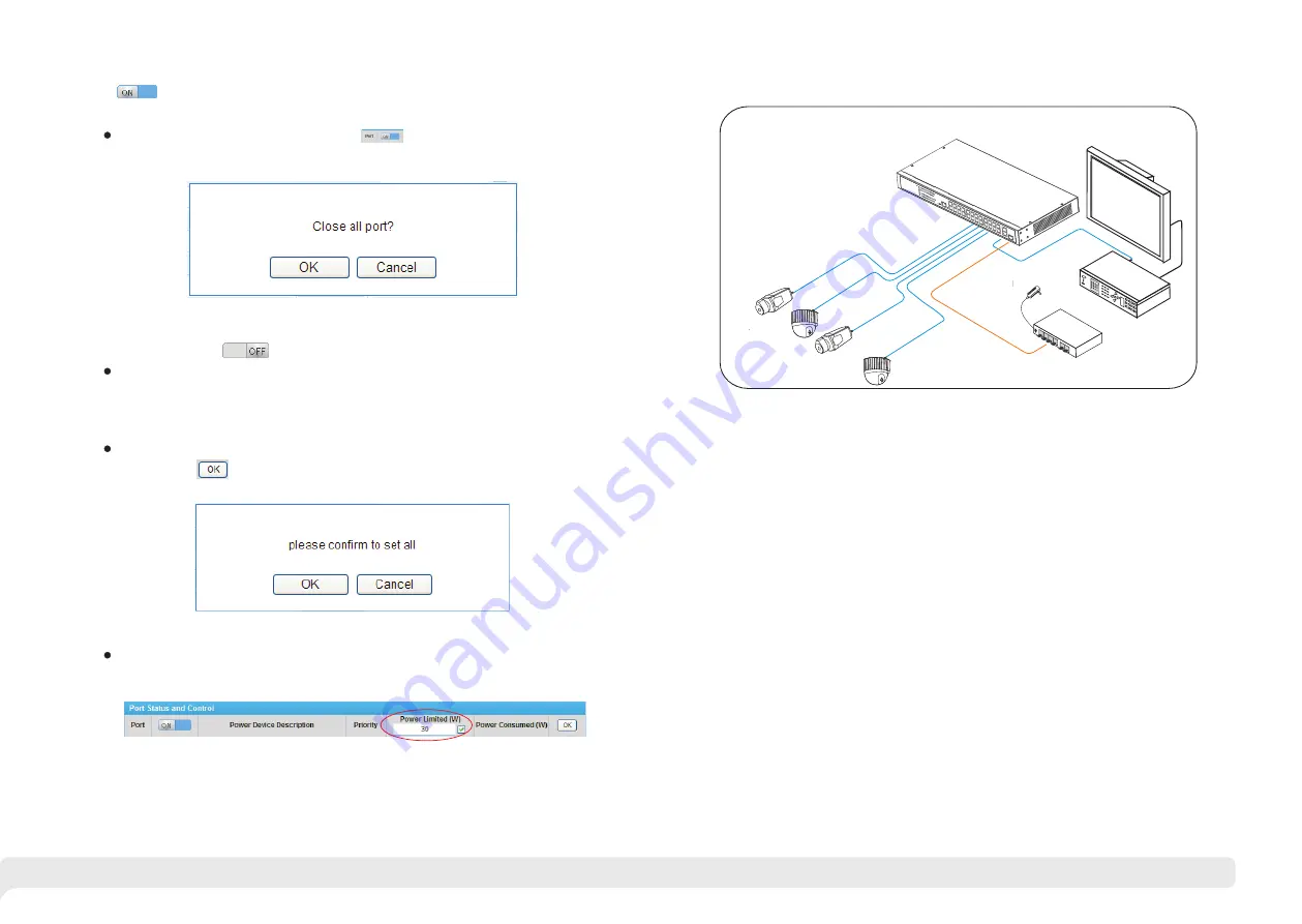
3.4 Typical Application 

This


product


design  is  environmental  friendly.  Please  store,  use  and  discard 

this  product    in  accordance  with  the  relevant  national  legal/  regulatory 

requirements.

E n vi ro nm en t pr ot ec ti on

Cat5/5e/6

LCD


display

NVR

switc

h

PoE


camera

PoE


camera

PoE


camera

PoE


camera

Summary of Contents for JAR-SW16-P300

Page 1: ...16 24 Ports PoE switch User Manual ...

Page 2: ... 1 1 2 Board Diagram 1 3 Specification 2 1 4 Product Feature 3 2 Installation 4 2 1 Shipping List 4 2 2 Installation Precautions 4 2 3 Installation Way 6 2 3 1 Rack Installation 6 2 3 2 Workbench Installation 7 2 4 Cable Connection 8 2 4 1 Device Connection 8 2 4 2 Configuration Cable Connection 2 4 3 Power Line Connection 3 PoE Web Management Page 3 1 Preparation Work 3 2 Set up Network Connectio...

Page 3: ...PoE Web Management Port PoE Output LED Reset PoE Output Percentage LED PoE Output Ports Reset PoE Web Management Port PoE Output LED Uplink Gigabit Ports PoE Output Percentage LED 24 Ports PoE switch AC100 240V Grounding Terminal 16 Ports PoE switch Provide 16 24x 100Mbps downlink PoE Ethernet ports 2x gigabit uplink Ethernet ports and 1x gigabit Fiber port Downlink Ethernet ports support PoE each...

Page 4: ...ng Terminal PoE Power Power Input Mains on load 100 240VAC 50 60Hz PoE Power Supply End span 1 2 3 6 IEEE802 3 af at PoE Max Power Output 250W 370W 340W if 110V AC input Single Port Power Output Voltage Single Port PoE Power Output 30W Voltage 54VDC PoE Web Management PoE Management Via Web Default IP Address 192 168 1 200 to check on off and adjust each port PoE output Reset Button PoE Web Reset ...

Page 5: ...ch may be affected by external interference outside the system through the ways of radiation and conduction Please pay attention to the followings AC power supply is TN system so it is necessary to use single phase power socket PE which can protect ground wire so that the filter circuit can effectively filter out the power grid disturbances The switch should work far away from high power radio tra...

Page 6: ...port switch when install the switch to the rack 2 3 2 Workbench Installation You can put this product on clean stable grounded workbench The installation procedure is as below 1 Put the device upside down carefully clean the grooves on the chassis backplane with soft cloth to make sure there is no oil or dust in it 2 Remove the stickers on the foot pad paste the foot pad in backplane groove 3 Put ...

Page 7: ...ourself Operation steps take Windows XP as sample 1 Click start to enter the start menu select control panel Double click network connection icon double click the local connection icon pop out local connection status window Make sure the management PC has already been installed with Ethernet adapter Use network cable to connect the console port with management PC Instruction 2 Click property butto...

Page 8: ...ernet option enter Internet option window 3 3 Operating Guidance of Web 3 3 1 Start and Login This product web default IP address 192 168 1 200 subnet mask 255 255 255 0 administrator account admin password admin After installing the equipment correctly and setting up the computer open the browser input the injector default address in the browser address bar then press the Enter key the user login...

Page 9: ... and wait for 10 seconds till product IP address is successfully changed 13 14 After inputting the correct user name and password click Login and the browser will show the product Web management page as the picture below Please follow the steps to check if the injector is installed correctly 1 Whether the physical connection of the equipment is correct The other end of the network line that is con...

Page 10: ...hat the computer IP address and the product IP address must be in the same network segment and the settings of subnet mask and gateway must be correct 2 When changing product IP address please ensure the power supply to avoid abnormal problems 3 What to do if you forget the IP address of the product Please refer to 3 3 2 5 restore the initial setting 3 3 2 3 Change Password Login password the prod...

Page 11: ...e power to be contributed decreases and the number of PoE equipments to be connected decreases on the contrary the more the number of PoE equipments to be connected the higher risk of system overload 4 Operation instructions after setting the value press OK button Setting succeeds when the following window pops out 3 3 2 9 Power Status Power status page diagram The input power allowing maximum ove...

Page 12: ... port and popup dialog box Take port 1 as an example press OK popup setup is successful When setting succeeds corresponding button becomes 1 Actual output total actual output power 2 Surplus the power to be used for redistribute Surplus input actual output reservation please noted that the product distributes power according to power level of detected PoE powered device when connecting a new PoE p...

Page 13: ...r setting parameters press OK button of the corresponding port then popup setting success when operation finishes Setting all the port parameters press port control and status actual output power W button then popup dialog box as shown below Press OK when all the setting finishes popup setup is successful Setting unified allowed maximum output power as shown below After selecting the check box all...

Reviews: