background image

Unpacking And Setting Up Server

Page 3

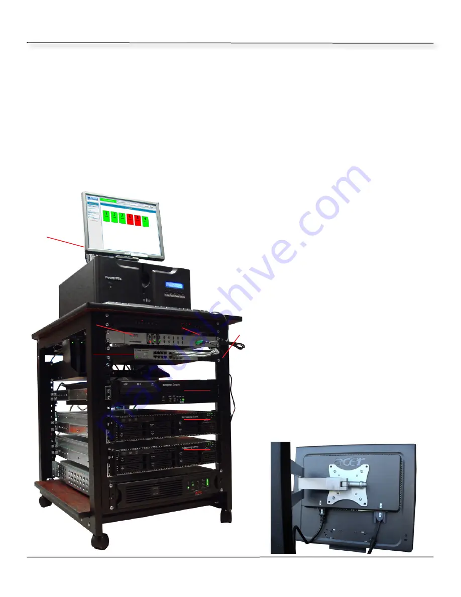
The picture to the lower left shows what a 200 channel digital computer server will look 

like completely set up. When your system arrives, the rack will come with the shelves 

(1)

router (aka switch) 

(2)

 and KVM 

(3)

 (used to view multiple computers with 1 monitor) 

already installed. Once you have the rack in the room you can start installing all the com-

puters, disc changer and computer monitor. Please do not rush and 

DO NOT UNDER ANY 

CIRCUMSTANCES PLUG IN THE SYSTEM BEFORE YOU COMPLETE ALL THE STEPS

. Each 

system comes with a “Management” computer 

(4)

 (Used to check income, change set-

tings, etc.). One “Processing” computer 

(5)

 (Used to convert the movie files into “Stream-

able” formats and streams content to booths).  If you have a 200 channel system, you 

will have an additional streaming computer 

(6)

. The “Management” computer 

(4)

 must 

be placed in the top set of rails of the rack as shown. The APC back up power supply goes 

on the bottom (pre installed) 

(7)

. The tall bracket on the back is used for the computer 

monitor 

(8)

 (which gets connected to the KVM switch). The Powerfile  

(9)

 is placed below 

the monitor. The key board and mouse  

go  in  front  of  the  powerfile 

(10)

. The 

wires  run along the right side and will 

get connected to the front of the KVM 

switch 

(11)

. The 24 port switch 

(2)


(also known as a switchable router) that 

is below the KVM is used for commu-

nications between your booths and the 

computers. If you have Quad with your 

system, there will be an 4 gray wires 

connected to the front of the switch. 

The switch is numbered and technically 

it doesn’t matter which port you plug in 

the booth cables to, but we suggest do-

ing them in order (helps with possible 

trouble shooting in the future).

The LCD screen is attached to the brack-

et with 4 screws that will be in a small 

bag tapped to the back of the monitor. 

Connect the power and 15 pin cable as 

shown. All cables throughout the system 

will be numbered for your convenience.

2

4

1

10

8

5

7

6

3

9

11

Summary of Contents for Xeon 1.1

Page 1: ...Digital System Installation Manual Revision Xeon 1 1 Technical Support Mon Fri 6am 5pm 619 670 4412 Extension 23 Emergency Support After Hours And Weekends 619 670 4412 Extension 69 ...

Page 2: ...verview Of The Server Page 4 Connecting Cables To Computers Page 5 Connecting STBs Page 6 Programming STBs Important Notice Operators of this digital system should be aware that Io Group Inc doing business as Titan Media and Manplay does not license or otherwise authorize the public dis play of its content ...

Page 3: ... always insure it When packaging a 20 or larger TV make sure you double box it Make sure the inner box with the TV has the picture tube facing DOWN If you do not understand something in the manual or have a problem please call our tech nical service department at 619 670 4412 or 800 878 4056 extension 8 Thank you for your continued patronage In the following pages you will find detailed directions...

Page 4: ...rails of the rack as shown The APC back up power supply goes on the bottom pre installed 7 The tall bracket on the back is used for the computer monitor 8 which gets connected to the KVM switch The Powerfile 9 is placed below the monitor The key board and mouse go in front of the powerfile 10 The wires run along the right side and will get connected to the front of the KVM switch 11 The 24 port sw...

Page 5: ...are connected to the proper jacks they are right next 2 3 to one another and if they are reversed the system will not work Make sure all cables are tight Cables that have Thumb Screws should be screwed in As a side note if you are having any issues with the system call us do not EVER un plug power from the computer after it is running Once your system is running and you have loaded a few discs we ...

Page 6: ...cts here 6 If you have Buddy glass or Buddy shutters in your booth the cable connected to the relay box or transformer would plug in here 7 This jack supplies the video signal to your main TV 8 9 The Ethernet jacks are used to connect your touch panels Both jacks work the same and either can be used 10 If you have Quad 2nd TV in each booth the BNC cable from the main server would plug in here usua...

Page 7: ...on box should change from Yellow to Blue 5 Now press the arrow down key 6 until the proper booth number appears 7 If you pass the number use the arrow up key 8 Once you have the correct booth number selected press the en 4 6 8 5 ter 4 button again The box around the Location box should change back to yellow 8 Now press the arrow down key again 6 The box around the Location box should turn blue and...

Reviews: