


Quick Operation Guide of Digital Video Recorder
3
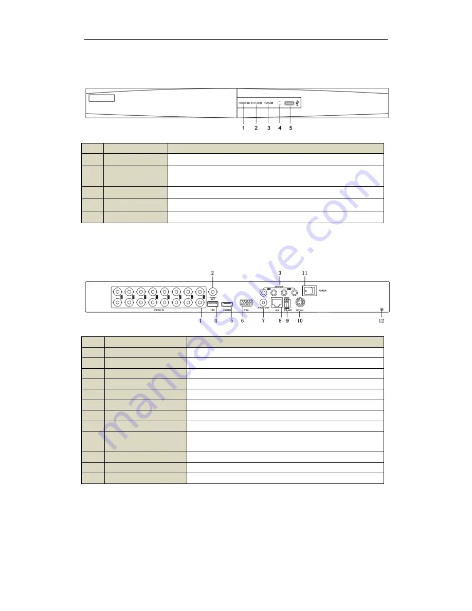
Front Panel
No.
Name
Function Description
1
POWER
POWER indicator turns green when DVR is powered up.
2
STATUS
STATUS indicator lights in red when data is being read from or written to
HDD.
3
Tx/Rx
Tx/Rx indictor blinks green when network connection is functioning properly.
4
IR Receiver
Receiver for IR remote.
5
USB Interface
Connects USB mouse or USB flash memory devices.
Rear Panel
No.
Item
Description
1
VIDEO IN
BNC connector for analog video input.
2
VIDEO OUT
BNC connector for video output.
3
AUDIO IN
RCA connector for audio input.
4
USB Interface
Connects USB mouse or USB flash memory devices.
5
HDMI
HDMI video output.
6
VGA
DB15 connector for VGA output. Display local video output and menu.
7
AUDIO OUT
RCA connector for audio output.
8
LAN Interface
Network interface.
9
RS-485 Interface
Connector for RS-485 devices. Connect the D+ and D- terminals to R+
and R- of PTZ receiver respectively.
10
12V
12 VDC power supply.
11
POWER
Switch for turning on/off the device.
12
GND
Ground (needs to be connected when DVR starts up).


