


Installation & operation manual
13
victr on ener gy
B L U E P O W E R
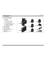
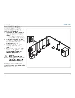
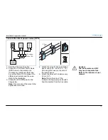
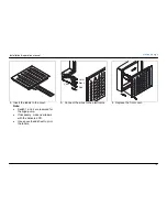
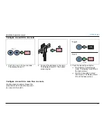
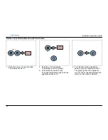
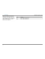
Connect the direct power nodes (DPN)
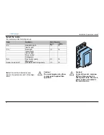
Fusebox
Max 10 A
DPN
12
11
12
11
30 cm
12"
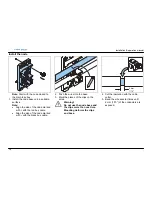
1. Start from the main fuse box.
2. Clamp the 10 A Direct Power Node
(DPN) wires to the instruments.
If necessary, install a multiple fuse
box with a total of 10 A between the
different instruments and the node.
Refer to the illustration.
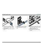
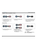
3. Clamp the 20 A DPN wires to the
bilge-pump.
Note:
Do not connect the wires to the
appliances mentioned.
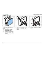
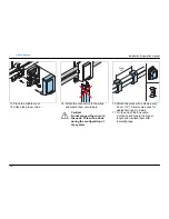
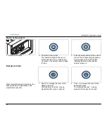
4. Attach the wires for the push button
panel. Leave 30 – 40 cm (12 – 16“)
extra length for easy connection of
the switch panel.
5. Attach the wires with a clamp every
30 cm (12“).
Note:
Clamp the wires of the
instruments, bilge-pump and switch
board separated from the bus cable.
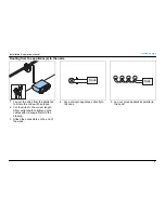
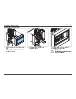
Caution!
The instruments and VHF
may need a separate fuse.
Refer to the instrument user
manual.


