background image

ADCP-90-606 Rev C

Page 1

www.commscope.com                                                                                                                                     © 2020 

CommScope.

 All Rights Reserved.

ADCP-90-606
Rev C, May 2020
commscope.com

User
Manual

INTRODUCTION   . . . . . . . . . . . . . . . . . . . . . . . . . . . . . . . . . . . . . . . . . . . . . . . . . . . . . . . . . . . . . . . . . . . . . . . . . . . . . . . . . . . . . . . 2

Trademark Information . . . . . . . . . . . . . . . . . . . . . . . . . . . . . . . . . . . . . . . . . . . . . . . . . . . . . . . . . . . . . . . . . . . . . . . . . . . . . 2

Standards Certification. . . . . . . . . . . . . . . . . . . . . . . . . . . . . . . . . . . . . . . . . . . . . . . . . . . . . . . . . . . . . . . . . . . . . . . . . . . . . . 2

Admonishments . . . . . . . . . . . . . . . . . . . . . . . . . . . . . . . . . . . . . . . . . . . . . . . . . . . . . . . . . . . . . . . . . . . . . . . . . . . . . . . . . . . . 3

General Safety Precautions  . . . . . . . . . . . . . . . . . . . . . . . . . . . . . . . . . . . . . . . . . . . . . . . . . . . . . . . . . . . . . . . . . . . . . . . . . . 3

RELATED PUBLICATIONS  . . . . . . . . . . . . . . . . . . . . . . . . . . . . . . . . . . . . . . . . . . . . . . . . . . . . . . . . . . . . . . . . . . . . . . . . . . . . . . 3

1

DESCRIPTION . . . . . . . . . . . . . . . . . . . . . . . . . . . . . . . . . . . . . . . . . . . . . . . . . . . . . . . . . . . . . . . . . . . . . . . . . . . . . . . . . . . . 3

1.1

General Description . . . . . . . . . . . . . . . . . . . . . . . . . . . . . . . . . . . . . . . . . . . . . . . . . . . . . . . . . . . . . . . . . . . . . . . . . . 3

1.2

Basic Components . . . . . . . . . . . . . . . . . . . . . . . . . . . . . . . . . . . . . . . . . . . . . . . . . . . . . . . . . . . . . . . . . . . . . . . . . . . 8

1.2.1

Panel Shell  . . . . . . . . . . . . . . . . . . . . . . . . . . . . . . . . . . . . . . . . . . . . . . . . . . . . . . . . . . . . . . . . . . . . . . . .   8

1.2.2

RapidReel Cable Spool Tray  . . . . . . . . . . . . . . . . . . . . . . . . . . . . . . . . . . . . . . . . . . . . . . . . . . . . . . . . .   9

1.3

Specifications and Dimensions . . . . . . . . . . . . . . . . . . . . . . . . . . . . . . . . . . . . . . . . . . . . . . . . . . . . . . . . . . . . . . . . 11

1.4

Accessory Kits  . . . . . . . . . . . . . . . . . . . . . . . . . . . . . . . . . . . . . . . . . . . . . . . . . . . . . . . . . . . . . . . . . . . . . . . . . . . . . 12

1.5

Typical Application  . . . . . . . . . . . . . . . . . . . . . . . . . . . . . . . . . . . . . . . . . . . . . . . . . . . . . . . . . . . . . . . . . . . . . . . . . 13

(continued)

Content

Page

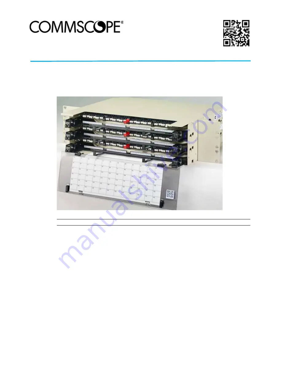
3RU/4RU Rapid Fiber Panel

Product QR code

Summary of Contents for 3RU

Page 1: ...n 2 Standards Certification 2 Admonishments 3 General Safety Precautions 3 RELATED PUBLICATIONS 3 1 DESCRIPTION 3 1 1 General Description 3 1 2 Basic Components 8 1 2 1 Panel Shell 8 1 2 2 RapidReel Cable Spool Tray 9 1 3 Specifications and Dimensions 11 1 4 Accessory Kits 12 1 5 Typical Application 13 continued Content Page 3RU 4RU Rapid Fiber Panel Product QR code ...

Page 2: ...ulled Through Conduit 45 8 BULKHEAD ADAPTER ACCESS PROCEDURE AND SERIAL NUMBER LOCATIONS 49 8 1 Accessing the Bulkhead Adapter Rear Connectors 49 8 2 Panel Shell RapidReel Cable Spool Tray and Microcable Labels 50 9 OPERATION 52 9 1 Connecting Patch Cords 52 9 2 RapidReel Cable Spool Tray Positions and How to Use Them 53 10 TECHNICALASSISTANCE 54 INTRODUCTION This manual describes the 3 and 4 Rack...

Page 3: ...capacity of 288 optical ports Figure 1 shows the 3RU panel Figure 2 shows the 4RU panel Danger Danger is used to indicate the presence of a hazard that will cause severe personal injury death or substantial property damage if the hazard is not avoided Warning Warning is used to indicate the presence of a hazard that can cause severe personal injury death or substantial property damage if the hazar...

Page 4: ... Reserved Figure 1 3RU Rapid Fiber Panel Figure 2 4RU Rapid Fiber Panel The Rapid Fiber Panel of a metal panel shell plus three or four RapidReel cable spool trays that are mounted within the panel shell 26181 A FRONT VIEW REAR VIEW 26180 A FRONT VIEW REAR VIEW ...

Page 5: ...s 2 mm or 900 micron in diameter up to nine feet 2 74 m in length terminated with 12 individual connectors These will be single mode SC UPC or APC single mode LC UPC or APC Each cable spool tray with plenum rated cable holds up to 200 feet of cable Cable lengths of up to 1000 feet are possible using a temporary external spool attached to the cable spool tray For shipment the cable spool trays and ...

Page 6: ...PANEL SHELL RapidReel CABLE SPOOL TRAY NOTE IF THE MICROCABLE ROUTES FROM THE FRONT INSERT THE CABLE SPOOL TRAY FROM THE FRONT IF THE MICROCABLE ROUTES FROM THE REAR INSERT THE CABLE SPOOL TRAY FROM THE REAR WHEN INSTALLING THE TRAY INTO A 4RU PANEL SHELL IT MAY BE NECESSARY TO LIFT THE UPPER TRAY TO ALLOW THE TRAY TO SLIDE IN 15 INCHES 38 1 CM CLEARANCE REQUIRED ON FRONT OR REAR OF PANEL SHELL TO...

Page 7: ...wound with a singlemode or multi mode indoor plenum rated cable The bulkhead is pre loaded with adapter packs The spooled cable is preterminated to the same bulkhead on the rear side The Rapid Fiber Panel mounts in either a 19 or 23 inch WECO or EIA equipment rack and requires 1 75 inches of rack space per RU A grounding point is provided on the left side of the panel shell for connecting a two ho...

Page 8: ...le assemblies Removable Front Cover Protects the equipment patch cords at the point where they enter the panel and connect to the adapter bulkhead One or two designation card are attached to inside of cover providing a means for identifying and recording connections Ground Connection Provides a point for securing a two hole lug used for connecting a grounding cable to the side of the enclosure Mou...

Page 9: ...le when loaded with one dual 3 0 mm plenum cable or one 12 fiber I O cable The 4RU spool can store up to 100 feet when loaded with one dual 3 0 mm plenum cable one 12 fiber plenum or I O cable or one 24 fiber plenum cable When the spool is unwound the cables are routed to an ODF or fiber panel Excess slack may be wound back onto the spool Note The factory pre installs the 23 inch mounting brackets...

Page 10: ...me position For a description of tray positions refer to Topic 9 2 on Page 53 Figure 7 Red Latch and Spool Locking Tab Microcable Assemblies Are loaded into each panel based on customer order Options for a particular panel include either single 12 fiber microcables or a dual microcable consisting of two 12 fiber subunits The microcables may be either single mode reduced bend radius RBR or multimod...

Page 11: ...ght 3RU 26 5 lb 12 0 kg With 100 ft of two dual 12 fiber microcables or with 200 feet of one dual 12 fiber microcable 4RU 37 7 lb 17 1 kg With 100 feet of dual 12 fiber microcable or with 75 feet of single 24 fiber microcable Mounting rack 19 inch or 23 inch EIA or WECO Recess options 2 4 or 5 inches 5 08 10 16 or 12 7 cm Number of ports per RU 12 SC or LC 24 SC or LC or 48 LC Front panel connecto...

Page 12: ...interbay management panel Environmental Operating conditions 23 F to 131 F 5 C to 55 C 5 to 85 RH No condensation Storage conditions 40 F to 158 F 40 C to 70 C 10 to 95 RH No condensation Table 1 Rapid Fiber Panel Specifications continued PARAMETER SPECIFICATION REMARKS 22 31 INCHES 56 67 CM 5 25 INCHES 13 34 CM 26179 A 22 96 INCHES 58 32 CM 3RU FRONT VIEW 4RU FRONT VIEW 17 42 INCHES 44 24 CM 5 0 ...

Page 13: ...e FPX panel Fiber jumper patch cords are used to connect the Rapid Fiber Panel to the active equipment Figure 9 Typical Rapid Fiber Panel Application 2 UNPACKING AND INSPECTION 1 Before installing the product open the shipping carton s and carefully unpack the contents 2 Check the panel for damages or missing ship along parts per the list provided in Topic 3 If there are damages contact TE Connect...

Page 14: ... 5 1 Mounting the Panel on the Equipment Rack Use the following procedure to mount the panel 1 If mounting a 3RU panel remove the three foam shipping inserts from the rear side of the panel as shown in Figure 10 and discard Note The Rapid Fiber Panel is designed to be installed in an environmentally controlled network telecommunications facility such as a Central Office Controlled Environmental Va...

Page 15: ...2 or 4 inch recess position Tighten screws to the torque specification shown in Figure 11 4 If the panel is being installed in a 19 inch rack or cabinet remove the 23 inch mounting brackets and install 19 inch brackets at the required recess 2 4 or 5 inches position as shown in Figure 11 Tighten screws to the torque specification shown in Figure 11 5 Secure the panel to the rack or cabinet using t...

Page 16: ...ovide at least 3 inches 7 6 cm of clearance at the panel s rear side as shown in Figure 12 to allow the spool to rotate freely when unwound Note Ground the unit to the local facility CBN Common Bonding Network or IBN Isolated Bonding Network per local practice 25782 A 12 24 SCREW AND WASHER 4 PLACES PROVIDE AT LEAST 3 INCHES 7 6 CM OF CLEARANCE AT THE REAR SIDE OF THE PANEL TO ALLOW THE SPOOL TO R...

Page 17: ...he red latches on the cable spool trays When a latch shipping brackets are present remove them using the following procedure 1 Remove the fiber tape from the front center of the panel as shown in Figure 14 Note that a single piece of tape straddles the multiple red latches of cable spool trays in the panel Figure 14 Removing Fiber Tape from Latch Shipping Brackets 26185 A RED LATCH LATCH SHIPPING ...

Page 18: ...he latch shipping bracket slightly enough to clear it from the red latch and move the shipping bracket to one side as shown in Figure 16 Figure 16 Withdrawing Latch Shipping Bracket 4 Press down gently on the fibers A to hold them in place while withdrawing the top tray latch shipping bracket B to prevent damage of fibers as shown in Figure 17 26186 A LATCH SHIPPING BRACKET BLUE TAPE 26176 A LATCH...

Page 19: ... from Tray 6 Push the red latch forward to return the cable spool tray back into the operational position 7 Continue down through the remaining cable spool trays removing the blue tape and latch shipping bracket from each of the trays Caution When removing the latch shipping brackets use caution to avoid damaging fibers 26187 A PRESS DOWN GENTLY ON FIBERS TO HOLD THEM IN PLACE WHILE REMOVING TOP T...

Page 20: ...e Rapid Fiber Panel front cover to provide clearance for the spool to rotate 2 Pull the red latch out to release the tray as shown in Figure 19 Figure 19 Pulling Red Latch Out to Release Tray 3 While holding the red latch out push the tray back slightly Continue pushing until the tray locks into pay out position as shown in Figure 20 Figure 20 Locking Tray Into Pay Out Position 25916 A RED LATCH 2...

Page 21: ...Method for Pulling Directly On Cable 5 Based on the location of other equipment at the site determine whether the cable would be best routed from the rear or front of the panel 6 If the cable will be routed from the rear of the panel start unwinding the internal spool by pulling on both the microcable connector pulling eye and or cable causing the internal spool and attached bulkhead panel to rota...

Page 22: ...of the panel shell at the points indicated in Figure 24 Save screws for reuse Note Provide at least 3 inches 7 6 cm of clearance at the rear side of the panel to allow the spool to rotate freely as the microcable is unwound Caution Avoid using excessive force when unwinding microcable from the internal spool Use the hand wrap method see Figure 22 if pulling on the cable by hand Caution If the cabl...

Page 23: ...de of the RapidReel cable spool tray and route the cable to the front as shown in Figure 26 d Guide the fanout assemblies or cabled module s into the empty panel from rear side and pull them through to the front It may be necessary to flatten the assembly within the pulling sock to allow it to pass through the panel e Align the slide in RapidReel cable spool tray with the rear of the panel shell N...

Page 24: ... lbs 0 7 Nm of torque 9 After unwinding the microcable ensure that the microcable is still within the cable retainer at the point where the microcable exits the panel 10 Using the red latch rotate the tray clockwise and pull the tray forward to the locked operation position as shown in Figure 27 Figure 27 Pulling Tray Forward to Locked Operation Position Note Be sure the microcable is pulled snug ...

Page 25: ...e cable spool trays are mounted within the panel shell Topic 6 3 on Page 33 The remaining microcable is unwound from the cable spool trays Topic 6 4 on Page 37 Note When mounting multiple Rapid Fiber Panels into a rack or cabinet be sure to calculate the total weight of all the equipment being mounted to verify that it does not exceed the rack or cabinet manufacturer s maximum weight allowance In ...

Page 26: ...ll in a cardboard shipment container mounted on a pallet Figure 29 Use the following procedure to unwind and route the cable from the external spool to an ODF or fiber panel Figure 29 Hand Carrying Shipment Container 1 Position the shipping pallet as close as possible to the equipment rack where the panel shell is to be installed The shipment container has hand holes on either side intended for us...

Page 27: ... shown in Figure 30 Figure 30 Cutting Banding Straps 3 Remove the straps as shown in Figure 31 Figure 31 Removing Straps Begin unpacking the shipment container as follows referring to Figure 32 a Open the top of the shipping container and remove the boxed panel shell b Lift off the shipping divider ...

Page 28: ...king Boxed Panel Shell and Shipping Divider 4 Lift up the shipment container and set it aside as shown in Figure 33 The external spools and RapidReel cable spool trays will remain on the pallet as shown 25927 A SHIPPING DIVIDER BOXED PANEL SHELL HAND HOLE FOR CARRYING SHIPPING CONTAINER ...

Page 29: ...ADCP 90 606 Rev C May 2020 Page 29 2020 CommScope All Rights Reserved Figure 33 Removing Shipping Container 5 Remove the spool stop fork lift protection Figure 34 ...

Page 30: ...re 22 on Page 21 pull all the far end connectors or cabled modules toward the termination location Figure 35 Proper Pulling Technique Note Each RapidReel cable spool tray has single or dual microcables depending on configuration order Note A small tag is attached to each microcable near the far end connector to identify the cable number and corresponding ports on the RapidReel cable spool tray ...

Page 31: ... other than the 5 inch recess position remove the 23 inch mounting brackets and re install them at the required 2 or 4 inch recess position Tighten screws to the torque specification shown in Figure 36 Note Due to space constraints in conduit only cables with MPO connectors or MPO like non functional connectors should be routed through conduit Note After the cables have been completely unwound fro...

Page 32: ...shell as shown in Figure 38 using the two screws and star washers provided Two locations are available see Figure 13 on Page 16 A two hole grounding lug shown here for reference is recommended for the connection Figure 38 Grounding the Rapid Fiber Panel Chassis Note Ground the unit to the local facility CBN Common Bonding Network or IBN Isolated Bonding Network per local practice 26201 A 12 24 SCR...

Page 33: ...spool assemblies may be installed in the panel shell from either the front or rear side After unwinding the microcables as far as possible toward the far end termination point return to the shipment pallet and unpack and install the RapidReel cable spool trays as follows 1 Use a box cutter to open the box on top of the external spool as shown in Figure 39 Figure 39 Opening Box on Top of External S...

Page 34: ... 44 4RU 288 fibers option Figure 42 3RU Panel Cable Spool Tray Mounting Slots and Port Designations Figure 43 4RU Panel Cable Spool Tray Mounting Slots and Port Designations 144 Fibers Option 26224 A LATCH SHIPPING BRACKET BLUE TAPE FIBER TAPE 26203 A CABLE SPOOL TRAY 1 PORTS 1 24 OR 1 48 CABLE SPOOL TRAY 3 PORTS 49 72 OR 97 144 CABLE SPOOL TRAY 2 PORTS 25 48 0R 49 96 FRONT VIEW 26219 A CABLE SPOO...

Page 35: ... position To move the panel into the cable payout position first pull out the red latch slightly to release the tray then while holding the red latch out push the tray back slightly and continue pushing until the tray locks into the payout position At this point the spool locking tab will no longer be protruding from the side of the panel and the cable can be paid out For an illustration and descr...

Page 36: ...lide the cable spool tray into the mounting slot until the stop is reached Figure 46 Aligning RapidReel Cable Spool Tray with Mounting Slot 3RU Panel Shown for Reference 7 Press the black release tabs on both sides of the panel shell as shown in Figure 47 and then continue sliding the cable spool tray into the mounting slot until it locks into place 26217 A FACTORY ROUTING REMOVE MICROCABLE FROM R...

Page 37: ... Bonding Screws 6 4 Unwinding Microcable from RapidReel Cable Spool Trays After the external spool has been paid out and the RapidReel cable spool tray installed in the panel shell the remaining microcable on the RapidReel cable spool tray can be unwound Use the following procedure to unwind the microcables from the internal spool 1 Open the panel front cover to provide clearance for the spool to ...

Page 38: ...lling Red Latch Out to Release Tray b While holding the red latch out push the tray back slightly Continue pushing until the tray locks into pay out position as shown in Figure 50 Figure 50 Locking Tray Into Pay Out Position c Remove blue tape that secures cable to the right rear of the panel as shown in Figure 51 25916 A RED LATCH 25939 A RED LATCH ...

Page 39: ...e panel to allow the spool to rotate freely as the cable is unwound Figure 52 Hand Wrap Method for Pulling Cable 4 After paying out cable as required do the following for each RapidReel cable spool tray Caution Use care and avoid using excessive force when unwinding microcable from the internal spool If the cable fails to unwind check for obstacles or obstructions that would prevent the spool from...

Page 40: ...ay Forward to Locked Operational Position c When done ensure the microcables are placed within the cable retainers 5 Locate and install the front port designation plates as shown in Figure 54 Slide in the designation plates until they reach the detents and snap into place Figure 54 Installing Front Designation Plates 3RU Panel Shown 6 Proceed to Topic 7 on Page 41 for guidelines on routing the mic...

Page 41: ...with a non functional connector proceed to step 6 If the microcable is terminated with connector fanout assemblies proceed to step 7 If the microcable is terminated with an NG4access cabled module proceed to step 8 5 Complete the following for each cable terminated with an MPO connector a Remove the pulling eye from each MPO connector by inserting and twisting a screwdriver or coin as shown in Fig...

Page 42: ...and the range of optical ports associated with the MPO connector Figure 56 Cable Number and Optical Port Designation Labels d When all the microcable MPO connectors are connected to the equipment MPO adapters proceed to step 9 6 Complete the following for each microcable terminated with a stub end non functional connector Note Do not cut off the non functional connector before cable installation h...

Page 43: ...is wrapped within a pulling sock such as shown in Figure 57 remove the pulling sock from the end of the microcable by first peeling away the tape and then cutting the two cable ties at the point shown Next slide the sock off the cable assembly and remove the pink bag from the connectors If a pipe protection is also present used for fanout assemblies with 900 micron fibers only remove the pipe refe...

Page 44: ...he appropriate adapter A label applied near the connector boot shown in Figure 58 indicates the connector s optical port Figure 58 Remove Pipes from 900 mm Fanout Assemblies d When all the individual connectors are connected proceed to step 9 8 If the microcable is terminated with an NG4access cabled module proceed as follows a If the microcable is being routed to an NG4access universal panel shel...

Page 45: ...ing Eye 3 Wrap several layers of vinyl tape around the pulling swivel and the trailing connector as shown in Figure 60 Note Due to space constraints in conduit only cables with MPO connectors or MPO like non functional connectors should be routed through conduit Note The swivel will ensure that proper pulling force is applied to the cable and will reduce the possibility of binding or tangling the ...

Page 46: ...igure 60 Wrap Pulling Swivel and Connectors with Vinyl Tape 4 Attach a draw wire or tape to the pulling swivel and then carefully guide the pulling swivel with attached connectors into the conduit Continue to guide the cable into the conduit while the cable is being pulled ...

Page 47: ...h a non functional connector proceed to step 11 10 Complete the following for each cable terminated with an MPO connector a Remove the pulling eye from each MPO connector by inserting and twisting a screwdriver or coin as shown in Figure 55 on Page 42 Note The minimum recommended conduit or firebreak hole diameter is 1 1 inch Note If the cable will be routed to a splice enclosure for splicing do n...

Page 48: ...minated with a non functional connector Figure 61 Cable Number and Optical Port Designation Labels a Record the label information cable number range of optical ports and serial number that is applied to each cable and then tag each cable so it can be identified when the cable jacket is removed for splicing b Cut off the non functional connector and discard c Determine the point at which the microc...

Page 49: ...s the connectors at the rear of the adapter bulkhead This should only be done following initial installation of the Rapid Fiber Panel and only if testing indicates that a connector may require cleaning Use the following procedure to access the connectors at the rear of the adapter bulkhead 1 Using the red latch carefully pull the adapter bulkhead forward until the stop position is reached Figure 6...

Page 50: ... push the red tab inward to slide the adapter bulkhead into its operational position Figure 62 Adapter Bulkhead Middle Tray in Rear Access Position 8 2 Panel Shell RapidReel Cable Spool Tray and Microcable Labels A superlabel that provides the product catalog number part number revision and date code is attached to the panel In addition a serial number label is attached to both the RapidReel cable...

Page 51: ...ALOG NUMBER PART NUMBER REVISION AND DATE CODE S N 1 1 144 S N 2 S N 3 3 RAPIDREEL CABLE SPOOL TRAYS PER PANEL 4 MPOs PER TRAY RAPID PANEL MPO 1 12 MPO 13 24 MPO 25 36 MPO 37 48 MPO 49 60 MPO 61 72 MPO 73 84 MPO 85 96 MPO 97 108 MPO 108 120 MPO 121 132 MPO 133 144 SPOOL 3 SPOOL 2 SPOOL 1 26222 A S N 1 S N 2 S N 3 PANEL SUPERLABEL CATALOG NUMBER PART NUMBER REVISION AND DATE CODE EACH CABLE IS LABE...

Page 52: ... damage the retina of the eye Do not look into the ends of any optical fiber Do not look directly into an optical adapter Exposure to invisible laser radiation may result An optical power meter should be used to verify active fibers A protective cap or hood MUST be immediately placed over any radiating adapter or optical fiber connector to avoid the potential of dangerous amounts of radiation expo...

Page 53: ...Positions and How to Use Them The cable spool tray has three positions operation home cable payout inward and full connector access outward The panel ships in the operation position with the spool locking tab protruding through the right side of the panel shell as shown in Figure 67 Figure 67 Operation Home Position Panel Shown With Top Cover Cut Away 26204 A PATCHCORDS CAN BE ROUTED EITHER UP OR ...

Page 54: ... slightly and continue pushing until the tray locks into the payout position At this point the spool locking tab will no longer be protruding from the side of the panel and the cable can be paid out 10 TECHNICALASSISTANCE To find out more about CommScope products visit us on the web at www commscope com For technical assistance customer service or to report any missing damaged parts visit us at ht...

Reviews: