6
6.
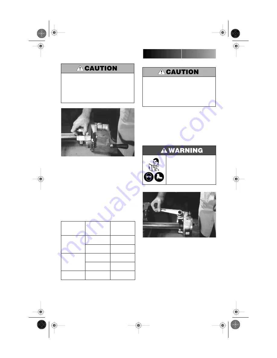
If groove diameter (“C” dimension) is not
within tolerance, the depth stop collar must be
adjusted to obtain the proper dimension. To
adjust for a
smaller groove diameter
, turn
the depth stop collars
counterclockwise
. To
adjust for a
larger groove diameter
, turn the
depth stop collars
clockwise
. A quarter turn
either way will change the groove diameter by
0.017" (0.068" per full turn).
7.
Prepare another trial groove and check the
groove diameter again. Repeat (Steps 4 and 5)
until groove diameter is within specification.
The “C” dimension (groove diameter) always
must conform to specifications under “Standard
Roll Groove Specifications – Steel and other IPS
Pipe”, page 9 to ensure proper joint performance.
Failure to do so could result in personal injury,
property damage, improper installation, joint
leakage or joint failure.
FEED RATES
Material
Wall Thick.
Inches/mm
Turns of Feed
Nut to Advance
the Feed
Steel and
Stainless Steel
0.065 to 0.109
1.65 to 2.76
¹⁄₂
turn
0.110 to 0.154
2.77 to 3.91
¹⁄₄
turn
Aluminum
0.065 to 0.109
1.65 to 2.76
²⁄₃
turn
0.110 to 0.154
2.77 to 3.91
¹⁄₃
turn
PVC
0.113 to 0.154
2.87 to 3.91
³⁄₄
turn
GROOVING PROCEDURES
Before grooving, make sure you have followed
all instructions in:
■
“Pipe Preparation” (page 4).
■
“Tool and Pipe Set Up and Operation”
(page 4).
■
“Mounting The Tool” (page 5).
■
“Adjusting The Groove Depth” (page 5).
1.
Advance the feed by turning the feed nut
clockwise by the amount shown in “Feed
Rates”, page 6. Feed rates for the VE12 vary
depending on material and pipe wall thickness.
The Victaulic VE12 tool is designed only for roll
grooving pipe of the appropriate sizes as listed un-
der “Tool Rating Chart” (page 10). Grooving of
pipe other than that recommended will result in
improper pipe end configuration or improper
groove dimensions for applying Victaulic prod-
ucts.
Before operating tool, review all
safety instructions on page 2.
Failure to do so may result in
serious personal injury.
VE12
TM-VE12.0743 Rev.A Page 6 Tuesday, May 29, 2001 6:04 PM


