background image


WARNING

•  Read and understand all instructions before attempting to install, remove, adjust, or maintain any Victaulic piping products.
•  Depressurize and drain the piping system before attempting to install, remove, adjust, or  maintain any Victaulic piping products.
•  Wear safety glasses, hardhat, foot protection, and hearing  protection.
Failure to follow instructions and warnings could cause  system failure, resulting in death or serious personal injury and property  damage.
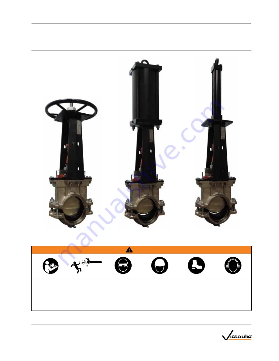
HANDWHEEL OPERATOR

PNEUMATIC OPERATOR

HYDRAULIC OPERATOR

I-795/906

REV_D

I-795/906

INSTALLATION AND MAINTENANCE INSTRUCTIONS

Series 795 and 906 Installation-Ready

 Knife Gate Valves

Summary of Contents for 795 Series

Page 1: ...intain any Victaulic piping products Wear safety glasses hardhat foot protection and hearing protection Failure to follow instructions and warnings could cause system failure resulting in death or serious personal injury and property damage HANDWHEEL OPERATOR PNEUMATIC OPERATOR HYDRAULIC OPERATOR I 795 906 REV_D I 795 906 INSTALLATION AND MAINTENANCE INSTRUCTIONS Series 795 and 906 Installation Re...

Page 2: ......

Page 3: ...eplacement Seat Cartridge 29 HAZARD IDENTIFICATION Definitions for identifying the various hazard levels are provided below When you see this symbol be alert to the possibility of personal injury Carefully read and fully u nderstand the message that follows DANGER The use of the word DANGER identifies an immediate hazard with a likelihood of death or serious personal injury if instructions includi...

Page 4: ...Knife 8 1 Retaining Plate 9 1 Packing Gland 10 4 Full Thread Hex Bolt 11 4 Washer 12 4 Heavy Hex Nut 13 4 Washer 14 4 Helical Spring Lock Washer 15 4 Hex Cap Screw 16 1 Dowel Pin 17 1 Dowel Pin 18 4 Hex Bolt 19 4 Helical Spring Lock Washer 20 4 Hex Nut 21 1 O Ring 22 1 Plug 23 8 Washer 24 2 Square Head Set Screw 25 2 Spacer Bolt 26 2 Retainer 27 2 Hex Cap Screw NOTES Items 10 11 and 12 comprise th...

Page 5: ...or 10 1 Slotted Spring Pin 11 1 Stroke Limiter Assembly 12 1 Washer 1 5 8 7 2 4 6 3 9 10 11 12 HANDWHEEL OPERATOR COMPONENTS 3 TO 8 INCH BEVEL GEAR COMPONENTS 10 TO 12 INCH 27 28 29 30 21 23 24 25 22 26 BILL OF MATERIALS Item Qty Description 21 1 Yoke 22 1 Gear Actuator 23 4 Washer 24 4 Helical Spring Lock Washer 25 4 Hex Cap Screw 26 1 Stem 27 1 Gate Connector 28 1 Slotted Spring Pin 29 1 Stroke ...

Page 6: ...asher 24 4 Helical Spring Lock Washer 25 1 Bushing 26 1 Gate Connector 27 4 Hex Cap Screw 28 4 Hex Nut 29 1 Stroke Limiter Assembly 30 1 Washer HYDRAULIC OPERATOR COMPONENTS BILL OF MATERIALS Item Qty Description 1 1 Yoke 2 1 Pneumatic Cylinder with Nuts 3 4 Washer 4 4 Helical Spring Lock Washer 5 1 Bushing 6 1 Gate Connector 7 1 Stroke Limiter Assembly 8 1 Washer PNEUMATIC OPERATOR COMPONENTS I 7...

Page 7: ...VE OPEN INSTALLED E C H F Nominal Size in DN Dimensions inches millimeters Weight lbs kg C E F H 3 0 88 10 25 6 75 32 25 113 00 DN80 22 4 260 4 171 5 819 2 51 3 4 0 88 11 25 6 75 34 75 122 00 DN100 22 4 285 8 171 5 882 7 55 3 6 1 13 13 75 7 00 43 75 166 00 DN150 28 7 349 3 177 8 1111 3 75 3 8 1 63 15 50 7 00 53 25 237 00 DN200 41 4 393 7 177 8 1352 6 107 5 I 795 906_7 REV_D ...

Page 8: ... INSTALLED VALVE OPEN INSTALLED VALVE OPEN INSTALLED E C H F B J Nominal Size in DN Dimensions inches millimeters Weight lbs kg B C E F H J 10 11 22 1 75 19 00 7 50 68 50 16 00 465 00 DN250 284 9 44 5 482 6 190 5 1739 9 406 4 210 9 12 11 22 2 00 21 00 7 50 73 00 16 00 497 00 DN300 284 9 50 8 533 4 190 5 1854 2 406 4 225 4 I 795 906_8 REV_D ...

Page 9: ...eters Weight lbs kg C E F H 3 0 88 10 25 6 75 42 00 126 00 DN80 22 4 260 4 171 5 1066 8 57 2 4 0 88 11 25 6 75 44 50 133 00 DN100 22 4 285 8 171 5 1130 3 60 3 6 1 13 13 75 7 00 53 75 215 00 DN150 28 7 349 3 177 8 1365 3 97 5 8 1 63 15 50 7 00 55 75 348 00 DN200 41 4 393 7 177 8 1416 1 157 9 10 1 75 19 00 7 50 79 50 550 00 DN250 44 5 482 6 190 5 2019 3 249 5 12 2 00 21 00 7 50 86 50 586 00 DN300 50...

Page 10: ...ters Weight lbs kg C E F H 3 0 88 10 25 6 75 43 88 115 00 DN80 22 4 260 4 171 5 1114 6 52 2 4 0 88 11 25 6 75 46 50 125 00 DN100 22 4 285 8 171 5 1181 1 56 7 6 1 13 13 75 7 00 55 00 172 00 DN150 28 7 349 3 177 8 1397 0 78 0 8 1 63 15 50 7 00 66 50 259 00 DN200 41 4 393 7 177 8 1689 1 117 5 10 1 75 19 00 7 50 80 25 462 00 DN250 44 5 482 6 190 5 2038 4 209 6 12 2 00 21 00 7 50 89 50 525 00 DN300 50 ...

Page 11: ...meters Weight lbs kg E F H 3 9 88 3 88 10 88 16 30 DN80 251 0 98 6 276 4 7 4 4 10 75 3 88 12 13 19 70 DN100 273 1 98 6 308 1 8 9 6 13 00 3 88 15 00 28 90 DN150 330 2 98 6 381 0 13 1 8 15 50 3 88 18 25 40 70 DN200 397 3 98 6 463 6 18 5 10 19 00 5 00 23 00 82 00 DN250 482 6 127 0 584 2 37 2 12 20 63 5 00 25 50 100 60 DN300 524 0 127 0 647 7 45 6 I 795 906_11 REV_D ...

Page 12: ...other piping system components RECOMMENDED SPARE PARTS AND TOOLS CAUTION Ensure that all spare seals and gaskets are compatible with the line temperature and media Failure to follow this instruction will cause gasket degradation resulting in joint leakage and property damage Spare Seat Cartridge Ratchet Wrenches Crescent Wrenches Pipe Wrenches Victaulic Lubricant or Silicone Lubricant Water Stabil...

Page 13: ...SECTION I Installing the 795 Valve Into a Steel Piping System Installing the 906 Valve Into an HDPE Piping System I 795_13 REV_D ...

Page 14: ...ult assembly and potential joint leakage 3 INSPECT PIPE GASKETS Check the pipe gaskets to ensure that they are suitable for the intended service The color code identifies the gasket grade Refer to Victaulic publication 05 01 in the G 100 General Catalog for the color code chart CAUTION A compatible lubricant must be used to prevent the pipe gaskets from pinching tearing during installation Pipe ga...

Page 15: ... property damage and could void the product warranty NOTE Do NOT discard the spacer bolts Reinstall the spacer bolts to finger tight after valve installation is complete If the valve must be removed from the system the spacer bolts will be necessary to separate housings and maintain spacing dimension C as defined in the dimension tables found on pages 7 10 between the bolt pads during storage ship...

Page 16: ...PADS Visually inspect the bolt pads at each joint to ensure that metal to metal contact is achieved across the entire bolt pad section 8 TIGHTEN 360 POSITIONING BOLTS Tighten the two 360 positioning bolts evenly by alternating sides until they reach a nominal torque of 40 ft lbs 54 23 N m I 795 906_16 REV_D ...

Page 17: ...turing the bolts or the bolt pads during installation DO NOT continue to tighten the nuts after the visual installation guidelines are achieved If the battery is drained or if the impact wrench is under powered a new impact wrench or a new battery pack must be used to ensure that the visual installation guidelines for the product are achieved Perform trial assemblies with the impact wrench and che...

Page 18: ...t in difficult assembly and potential joint leakage 3 INSPECT PIPE GASKETS Check the pipe gaskets to ensure that they are suitable for the intended service The color code identifies the gasket grade Refer to Victaulic publication 05 01 in the G 100 General Catalog for the color code chart CAUTION A compatible lubricant must be used to prevent the pipe gaskets from pinching tearing during installat...

Page 19: ... visual check is required to ensure that the seat meets the pipe ends 5c REMOVE ONLY THE SPACER BOLTS There is one spacer bolt on each bolt pad to maintain spacing between the bolt pads during shipping and assembly After inserting pipe remove only the spacer bolts and the attached warning tags before tightening the four nuts in step 6 CAUTION Spacer bolts are designed to keep the valve s housings ...

Page 20: ...ch with a deep well socket can be used to bring the bolt pads into metal to metal contact Refer to the Series 906 Helpful Information and Impact Wrench Usage Guidelines sections WARNING Visual inspection of each joint is critical Improperly assembled joints must be corrected before the system is placed into service Failure to follow these instructions could cause joint failure resulting in serious...

Page 21: ...ity with the impact wrench to avoid damaging or fracturing the bolts or the bolt pads during installation DO NOT continue to tighten the nuts after the visual installation guidelines are achieved If the battery is drained or if the impact wrench is under powered a new impact wrench or a new battery pack must be used to ensure that the visual installation guidelines for the product are achieved Per...

Page 22: ...This page intentionally blank ...

Page 23: ...SECTION II Maintenance Removing the Seat Cartridge Installing the Seat Cartridge ...

Page 24: ...locking pin referenced on page 17 through the yoke page 5 item 1 into the gate connector page 5 item 9 Disconnect the threaded stem page 5 item 7 from the gate connector by removing the slotted spring pin page 5 item 10 Cycle the threaded stem independent of the gate connector then replace the slotted spring pin and remove the lockout bolt For pneumatically or hydraulically operated valves refer t...

Page 25: ... remove the nut on the T bolt clamp and pull the clamp apart 2b Remove the T bolt clamp and split the two halves of the stroke limiter to remove Remove 3 REMOVE PLUG Using a 11 4 inch 32 mm wrench for the 3 to 8 valves or a 11 2 inch 38 mm wrench for the 10 to 12 valves remove the plug from the bottom of the valve body I 795 906_25 REV_D ...

Page 26: ...he knife then finger tighten This is necessary to attach the seat to the knife during removal in later steps Valve Size Retaining Plate Bolt Size Retaining Plate Socket Size inches mm 3 8 7 16 5 8 inch M16 Bolt 3 4 inch M19 Nut 10 12 3 4 11 8 inch M29 Bolt 11 8 inch M29 Nut 5 REMOVE RETAINING BOLTS Remove the four hex cap bolts and nuts from the retaining plate as shown above NOTE Do NOT remove th...

Page 27: ...ed seat cartridge to slide out of the gate connector prematurely Failure to follow this instruction could result in personal injury or property damage 6b For pneumatically or hydraulically operated valves actuate the valve open to draw the seat out from the valve body CAUTION Support the seat cartridge during actuation to prevent lateral movement Though the valve is operable in any orientation ang...

Page 28: ...hen removing the seat cartridge be prepared to support its weight with both hands Refer to the table on page 11 for specific weights before attempting to remove the seat cartridge Larger sizes may require the use of mechanical lifting equipment Sealing Faces 8 CLEAN VALVE Ensure that the seat cavity and drain plug are free from debris by flushing the cavity with water Wipe clean the sealing faces ...

Page 29: ...ior surfaces of the new seat cartridge NOTE The seat contains a tab that must be installed facing the slot in the valve body as shown above 1b Add a thin coat of anti seize compound to the top of the knife as shown to the right to aid with installation and with future removal of the cartridge Apply anti seize compound 2 INSERT CARTRIDGE Slide the replacement seat cartridge into the slot in the gat...

Page 30: ...sed to bring the seat toward the valve body WARNING Keep hands away from the edges of the knife seat while replacing it into the valve body Keep hands away from the seat cartridge and yoke while actuating the valve Failure to follow this instruction could result in personal injury 4 REPLACE RETAINING BOLTS When the retaining plate is 1 inch 25 mm or less from the valve body insert the four hex cap...

Page 31: ...the stroke limiter on the stem by reversing the procedure for removal Do not tighten the T bolt clamp past 75 in lbs CAUTION DO NOT attempt to place the valve back in service without replacing the stroke limiter Failure to follow these instructions will cause damage to the valve components This may result in joint leakage or property damage and could void the product warranty 9 INSPECT GAP Operate...

Page 32: ...or complete contact information visit victaulic com I 795 906 8413 REV D UPDATED 6 2017 Z000795000 VICTAULIC AND INSTALLATION READY ARE REGISTERED TRADEMARKS OR TRADEMARKS OF VICTAULIC COMPANY AND OR ITS AFFILIATED ENTITIES IN THE UNITED STATES AND OR OTHER COUNTRIES 2017 VICTAULIC COMPANY ALL RIGHTS RESERVED ...

Reviews: