Viconics VT7600E Series Installation Manual Download Page 9

9

 | 028-0363-03 


                                                           November 2015

u

ser

 i

nTerface

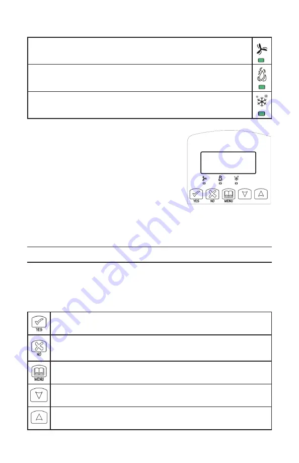
When any of the fan is ON, the FAN LED will illuminate

When heating & reheat is ON, the HEAT LED will illuminate

When cooling is ON, the COOL LED will illuminate

User configuring instructions menu

The VT76X6E series of controllers feature an intuitive, 

menu-driven, back-lit LCD display that walks users 

and installers through the configuring steps, making 

the configuring process extremely simple. This menu 

is typically accessed by the user to set the parameters 

such as the clock time set, the schedule time events 

and the system mode.
It is possible to bring up the user menu at any time 

by depressing the MENU key. The status display 

automatically resumes after exiting the user-configuring menu.
If the user pauses at any given time during configuring, 

Auto Help

 text is displayed to 

help and guide the user through the usage and configuring of the controller.

Ex.:


Press yes key to change cooling temperature setpoint

Use the up or down arrow to adjust cooling setpoint

Local keypad interface

Each of the sections in the menu is accessed and configured using 5 keys on the 

Room Controller cover.
The priority for the alarms is as follows:

The YES key is used to confirm a selection, to move onto the next menu 

item and to manually scroll through the displayed information. 

The NO key is used when you do not desire a parameter change, and to 

advance to the next menu item.  Can also be used to toggle between heat-

ing and cooling setpoints. 

The MENU key is used to access the Main User Menu or exit the menu. 

The down arrow key is used to decrease temperature setpoint and to adjust 

the desired values when configuring the Room Controller. 

The up arrow key is used to increase temperature setpoint and to adjust the 

desired values when configuring the Room Controller. 

Summary of Contents for VT7600E Series

Page 1: ...cation and Function 3 Screw terminal arrangement and wiring 3 Typical applications 4 Main outputs wiring 4 Remote sensor accessories 5 Configuring and Status Display Instructions 7 Status display 7 Us...

Page 2: ...ntroller Installation 1 Swing open Room Controller PCB to left by pressing PCB locking tabs Fig 2 2 Pull out cables 6 out from wall En sure wall surface must is and clean 3 Insert cable in central hol...

Page 3: ...ents have undergone rigorous tests and verification prior to shipping to ensure proper and reliable operation in the field Whenever a control failure could lead to personal injury and or loss of prope...

Page 4: ...eparate equip ment with a different power supply feed external switched power leg through RH without installing a jumper across RC RH 7 Heat 1 W1 Output for heating stage number 1 8 Heat 2 W2 Output f...

Page 5: ...rectifier Reference of the control signal is the common of the power supply of the Room Controller Terminal C Note 3 Electromechanical contacts are to be used with the digital inputs Electronic triac...

Page 6: ...2 29 20 161 1499 9 16 51 3692 11 52 18 8277 31 88 7 7360 51 124 3 4857 28 18 151 6239 8 18 48 7042 12 54 17 9636 32 90 7 4182 52 126 3 3568 27 17 142 7211 7 19 46 1933 13 55 17 1440 33 91 7 1150 53 12...

Page 7: ...ttended the Room Controller has an auto scrolling display that shows the current status of the system Each item is scrolled sequentially with the back lighting in low level mode Pressing any key will...

Page 8: ...ms is as follows Sequence of manual scroll status display Manual scroll of each menu item is achieved by pressing the Yes scroll key re petitively The last item viewed will be shown on the display for...

Page 9: ...lp text is displayed to help and guide the user through the usage and configuring of the controller Ex Press yes key to change cooling temperature setpoint Use the up or down arrow to adjust cooling s...

Reviews: