Circuit diagrams
51
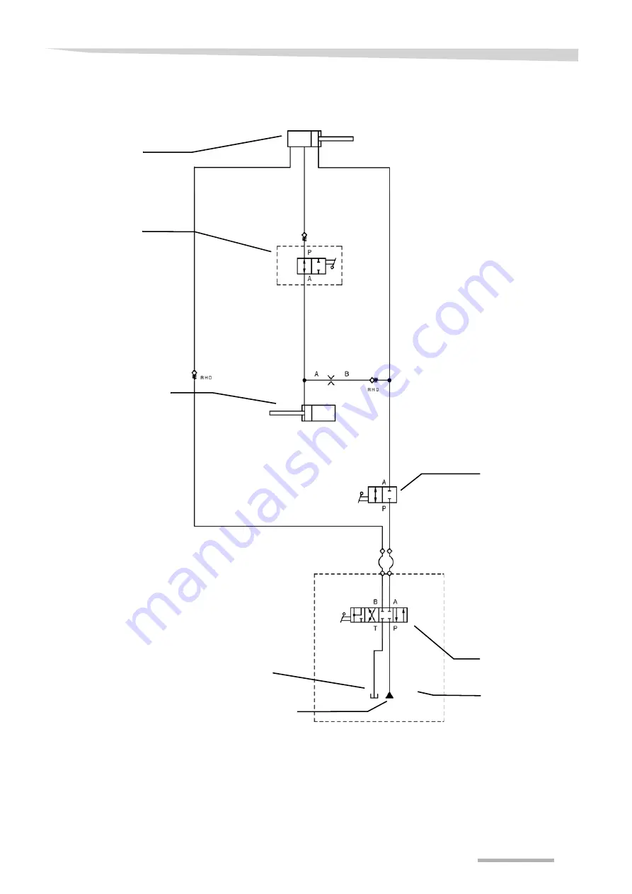
Hydraulics circuit
diagram
Tank line
Tractor
Double-acting control device with return flow
Ball valve
Pressure line
Hydraulic cylinder, rear
OptionHydraulic
single lift [+]
Hydraulic cylinder,
front
Page 1: ...Andex 694 EVO Assembly instructions Original assembly instructions Edition 04 2011 Date of print 01 2013 Language EN Machine number VF69650651 Model 6965 Document number 16648188 EN ...
Page 2: ... or parts of this manual without the explicit permission of Kverneland is not permitted All rights reserved The contents of these assembly instructions are subject to change without notice The right to technical revision is reserved Kverneland Group Kerteminde AS Taarupstrandvej 25 DK 5300 Kerteminde Denmark Tel 45 65 19 19 00 ...
Page 3: ...and lifting arms 27 Hydraulics 29 Rotor 31 Drive 38 Lighting equipment and electrics 39 Attachment parts 40 Fitting the rear swath former 42 Fitting the front swath former 43 Setting up work 45 PTO shaft length 45 Steering 47 Fitting the tine supports 48 Adjusting the rotor pitch 48 Accessories 50 Circuit diagrams 51 Lighting equipment circuit diagram 52 Final operations 53 Checking 53 ...
Page 4: ... must familiarise yourself with the contents of these assembly ins tructions before assembly or operating the machine In this way you will achieve optimum work results and operational safety The assem bly instructions form an integral part of the machine and must always be kept to hand This will allow accidents to be avoided warranty requirements to be met For the employer Untrained or unauthorise...
Page 5: ... information The Examples pictogram indicates examples that assist understan ding of the instructions The spanner indicates tips for assembly or adjustment work This arrow in the diagram shows the direction of travel The brush indicates the points that must be lubricated using the brush The grease gun indicates the points that must be lubricated using the grease gun Switch on the tractor Secure th...
Page 6: ...lations All personnel involved in the assembly must be aware of these rules and regulations and adhere to them they must also be instructed on the potential risks and dangers Unauthorised alterations to the machine invalidate any liability of the manufacturer for resultant damage The following rules and regulations must be observed The locally applicable accident prevention regulations Recognised ...
Page 7: ... Wear sturdy footwear and prescribed protective equipment Support and secure the machine carefully during assembly Particular care must be taken in dealing with energy accumulators such as springs and hydraulic or compressed air assemblies Dispose of oils grease and filters in accordance with regulations Protective equipment must be properly attached and swung into its protective position Actuatio...
Page 8: ... bottom Rotation about a horizontal axis viewed at right angles to the direction of travel from left to right The rotation of screws and nuts etc is always viewed from the operating side 8 8 10 9 12 9 M 6 9 9 Nm 7 3 ft lbs 14 Nm 10 3 ft lbs 17 Nm 12 5 ft lbs M 8 24 Nm 17 7 ft lbs 34 Nm 25 ft lbs 41 Nm 30 3 ft lbs M 10 48 Nm 35 4 ft lbs 68 Nm 50 2 ft lbs 81 Nm 59 8 ft lbs M 12 85 Nm 62 7 ft lbs 120...
Page 9: ... carrier Sustainer Transport holder for tine supports Main frame Rotor arm Rear swath former Deflector bridge Transport chassis Rotor chassis Main drive Deflector bar Lift limiter T gear box Steering arm Lifting arm console Steering Front swath former Tine support ...
Page 10: ...ain drive PTO shaft Deflector bar Lifting arm control rod Front main frame Rotor chassis wheels Transport chassis wheels Rotor Auxiliary drive PTO shafts Transport chassis frame Transport chassis axles Right deflector carrier Lifting arms with hydraulic cylinder Steering linkage T gear box Left deflector carrier ...
Page 11: ...2 pcs M10 x 30 12 pcs M 16 x 60 Cover caps for rotor chassis wheels Assembly kit for flange bearing Fastening clamp for front hydraulic connection 23 lynch pins 2 traction ropes 6 m and 9 m 6 pcs M 16 x 140 4 flange bearings Assembly kit for lifting arm transport locking bar ...
Page 12: ...ting arm Lift cylinder 2 3 4 5 7 1 3 6 6 8 Lifting arm console No Assembly group Page 1 Connect front main frame with rear main frame 16 2 Connect main frame with transport chassis 14 3 Fit left and right lifting arms to lifting arm console 27 4 Fit bearing housing onto left lifting arm 33 5 Fit bearing housing to right rotor 34 6 Fitting the rotors onto the lifting arms 36 7 Fit gear box to main ...
Page 13: ...REPORT MISSING PARTS form and send it to the ORDER DESK in Kerteminde straight away Removing the surface protection Remove the surface protection e g Tectyl with which the bare surfaces such as tine arms tine supports and bearing shafts have been coated Grease the bare surfaces using a brush Observe the safety information Observe the safety information when carrying out all work Disre gard for saf...
Page 14: ... and wheels into the transport chassis and secure Fit the wheels of the transport chassis onto the axles Fit the steering arms then adjust them and screw into place Rear main frame Transport chassis Steering arm Axle No Quantity Part 1 1 Transport chassis 2 6 M 16 x 140 bolts 10 9 3 12 M 16 nuts 10 9 4 18 M 16 washers 5 2 Axles 6 2 10 0 75 15 3 wheels 7 2 Steering arm 8 2 M 16 x 80 bolts 10 9 9 2 ...
Page 15: ... pins Wheel chock M 18 wheel nuts x 1 5 270 Nm M 16 x 140 10 9 M 16 290 Nm Spacer sleeve Spacer sleeve Drive in the dowel pins at 90 to each other Reflector 30 cm above driving surface M 16 x 120 8 8 M 16 210 Nm M 16 x 80 10 9 ...
Page 16: ...stand Raise the front main frame with lifting accessories and secure At the flange piece screw the front main frame to the rear main frame torsion free Fit the PTO shaft holder PTO shaft holder Front main frame Rear main frame No Quantity Part 1 1 Rear main frame 2 1 Front main frame 3 12 M 16 x 60 bolts 4 12 M 16 nuts 5 24 M 16 washers 6 1 PTO shaft holder Rear main frame Stand Front main frame ...
Page 17: ...grease the running surfaces on the sustainer Fitting the hose guide Fit the hose guide onto the attachment carrier Sustainer Front main frame No Quantity Part 1 1 Sustainer with assembly material Hose guide No Quantity Part 1 1 Hose guide 2 1 Perforated plate 3 2 M 10 x 30 rounded head bolts 4 2 11 x 20 x 2 washers 5 2 Self locking nuts ...
Page 18: ...ables in the front cable duct Fit the front cable duct with hydraulic hoses and electrical cables under the main frame Fit the PTO shaft holder and deflector bridge No Quantity Part 1 1 Front cable duct 2 2 M 8 x 16 thread rolling bolt Front cable duct Hydraulic hoses and electrical cables ...
Page 19: ...left and right steering rods to the steering arms See Fitting the left and right steering rods page 20 Connect the front steering rod See Fit the front steering rod page 21 Connect the centre steering rod See Fitting the centre steering rod page 21 Connect the rear steering rod See Connecting the rear steering rod page 23 Front steering rod Rear steering rod Swinging arm Right steering rod Left st...
Page 20: ...n with a self locking nut Right steering rod Left steering rod Do not tighten the self locking nut on the block The steering rods must be fitted within the swinging arm in such a way that they are secure yet still free moving Otherwise the ma chine may be damaged No Quantity Part 1 1 Right steering rod 2 1 Left steering rod 3 1 Locking plate 4 1 M 8 x 20 bolt 5 1 M 8 self locking nut 6 2 Threaded ...
Page 21: ...ng rod through the bearing shells Fit the clevis on the centre steering rod facing in the forward drive direction Connect the clevis of the centre steering rod to the adapter of the front and rear steering rods Fit the pins front and rear and secure using the split pin Pin Front steering rod No Quantity Part 1 1 Front steering rod 2 1 Pin 3 1 5 x 28 dowel pin 4 1 8 x 30 dowel pin Clevis Centre ste...
Page 22: ...Insert the threaded pin Secure the threaded pin with a self locking nut Clevis Centre steering rod Bearing shell Rear steering rod Do not tighten the self locking nut on the block The steering rods must be fitted in such a way that the clevis is se cure yet still free moving Otherwise the machine may be dama ged No Quantity Part 1 1 Front steering rod 2 1 Centre steering rod 3 1 Threaded pin 4 1 M...
Page 23: ...ure with self locking nut Fit the clevis to the outside of the right track rod Insert the pin into the track arm and secure with self locking nut Attach the protective cap Check the tracking and adjust if necessary See Checking the track page 24 Rear main frame Clevises Right track rod Swinging arm No Quantity Part 1 1 Right track rod 2 1 Clevis 3 2 Pin 4 2 M 16 self locking nut 5 2 Protective cap...
Page 24: ...1 015 mm Check track A at the front and rear sides of the tyres Front A Rear A 3 mm Track arm Steering arm Track rod Steering rod Contact your dealer if specifications differ Never carry out any work on the steering or tracking yourself Front steering rod L1 2 344 mm A A 3 mm S S Rear steering rod L3 2 344 mm Track rod S 1 015 mm Middle steering rod L2 2 566 mm Front steering rod not adjustable On...
Page 25: ...travel to the intermediate shaft support The oval protective pot points to the right in relation to the direction of travel to the auxiliary drive shaft support Use a brush to grease all the PTO stub shafts Fit the first T gear box with protective pots to the transmission console When doing so fit the spacers from above using bolts No Quantity Part 1 1 T gear box with protective pots 2 4 M 12 x 40...
Page 26: ...g 26 Fit the support for the front swath former to the first T gear box No Quantity Part 1 1 Support for swath former carrier 2 2 M 12 x 40 bolts 3 1 Washers 4 2 Spacers Support for swath former carrier Spacers Bolts ...
Page 27: ...ft label onto the left hand side of the implement Fit the lifting arm with the ball valve onto the right hand side of the implement Screw flange pieces in place Distance ring Flange piece Lifting arm support Distance ring No Quantity Part 1 2 Lifting arms 2 4 Flange piece 3 4 Distance rings 5 16 M 12 x 45 bolts 6 16 M 12 self locking nuts 7 24 M 12 washers 8 8 M 8 x 45 bolts 9 8 M 8 washers 10 8 M...
Page 28: ...miters Ensure that the lift limiters can swing freely Adjust the lift limiters with the washers Fit the spring for the lift limiter Hydraulic cylinder Lift limiter Pin No Quantity Part 1 2 Transport locking bars and washers 2 2 Pin 3 20 31 x 45 x 2 washers 4 2 31 x 45 x 1 washers 5 4 Dowel pins Lift limiter Hydraulic cylinder Spring 31 x 45 x 2 washers Pin Dowel pin Dowel pin Dowel pin ...
Page 29: ...Crate packaging 29 Hydraulics Lay the hydraulic hoses and screw them firmly in place Pay attention to the numbering of the hydraulic hoses ...
Page 30: ...es through the ceramic eyelet on the attachment carrier Push the rope stopper on to the control cable and secure the knots Secure the traction ropes with the rope stopper so that they are slightly tensioned when the lifting arm is lowered Control cable Ceramic eyelet Transport locking bar No Quantity Part 1 1 Control cable 9 m left lifting arm 2 1 Control cable 6 m right lifting arm Ceramic eyelet...
Page 31: ... the middle hole pattern of both rotor chassis Adjust the rotor pitch See Adjusting the rotor pitch page 48 Tighten the wheel nuts on the wheels to 20 Nm Fit cover caps to wheels No Quantity Part 1 2 Pre assembled rotor chassis with rotor gear and bearing housing 2 8 16 x 6 5 wheels 3 8 Cover caps 20 Nm wheel nut Wheel Bearing housing Rotor gear Double wheel ...
Page 32: ... to both rotor gears No Quantity Part 1 23 Rotor arms 2 23 M 12 x 60 bolts 3 46 M 12 washers 4 46 M 12 self locking nuts 5 23 M 12 x 75 bolts 6 46 Shims 7 23 Washers 35 x 52 x 3 5 Rotor arm Shim M 12 self locking nut 120 Nm M 12 self locking nut 70 Nm M 12 washer Washers 35 x 52 x 3 5 M 12 x 75 bolt M 12 x 60 bolt Rotor gear ...
Page 33: ...sher and ring onto the bearing shaft Secure the ring with a dowel pin Drive in the dowel pins at 90 to each other No Quantity Part 1 1 Left bearing housing 2 1 Washer 45 x 55 x 1 3 1 Ring 4 1 Dowel pin large 5 1 Dowel pin small 6 1 Washer for bearing shaft Bearing shaft Bearing housing Washer Ring Dowel pins Washer for bearing shaft Drive in the dowel pins at 90 to each other ...
Page 34: ...ush to grease the PTO stub shaft Fit the bearing housing onto the right rotor gear using Ripp screws No Quantity Part 1 1 Right bearing housing 2 4 M 14 x 70 Verbus Plus bolts 3 4 Spacer sleeves Rotor gear Bearing housing Verbus Plus bolts PTO stub shaft Spacer sleeve ...
Page 35: ...se the machine to the headland position Turn the rotor by hand to check that it is rotating correctly Distance from possible collision points min 150 mm Using the pendulum support adjust the position of the rotor m ax 900 m m Adjusting screw 1 2 3 4 No Quantity Part 1 1 Pendulum support 2 1 Pin 3 2 26 x 38 x 2 washers 4 2 Spring cotter pins Checking the clearance distances In the headland position...
Page 36: ...haft Push the washer and ring onto the bearing shaft Secure the ring with a dowel pin Drive in the dowel pins at 90 to each other No Quantity Part 1 1 Right rotor with bearing housing 2 1 Washer 45 x 55 x 1 3 1 Ring 4 1 Dowel pin large 5 1 Dowel pin small 6 1 Washer for bearing shaft Bearing shaft Right bearing housing Ring Dowel pins Washer Washer for bearing shaft Drive in the dowel pins at 90 t...
Page 37: ... locking device for the left rotor onto the deflector carrier The crank locking device for the right rotor is already fitted to the bearing housing No Quantity Part 1 1 Left rotor 2 Left lifting arm with bearing housing 3 4 M 14 x 70 Verbus Plus bolts 4 4 Spacer sleeves Left lifting arm Rotor with bearing housing Bolts PTO stub shaft Spacer sleeve Crank locking device Crank No Quantity Part 1 2 Cr...
Page 38: ...ng schedule for PTO shafts Intermediate shaft Auxiliary drive shaft No Quantity Part Greasing interval 1 1 WWE 2280 drive shaft 100 Wide angle joint daily 2 1 ZW 2300 intermediate shaft 100 3 1 W 2200 auxiliary drive shaft for the right rotor 100 4 1 DG 2200 double joint 100 5 1 W 2300 auxiliary drive shaft for the left rotor 100 ...
Page 39: ...through the opening in the transport chassis on the frame Use cable ties to fix the cables to the lashing eyes on the transport chassis Route the long cable starting from the front hose guide beneath the main frame Secure the cable with a cable tie Warning plates No Quantity Part 1 2 Warning sign and lighting equipment set Cable set Connector Cable set Rear light Ensure the correct position of the...
Page 40: ...crank locking device to the left deflector carrier The crank locking device on the right rotor is already fitted Fit the deflector bar onto the deflector carrier Bearing housing Deflector carrier Crank locking device No Quantity Part 1 2 Deflector carrier 2 2 M 12 x 45 bolts 3 8 M 12 self locking nuts 4 8 M 12 washers 5 2 Crank locking device 6 6 M 12 x 35 bolt 9 2 Deflector bridge for rotors 10 4...
Page 41: ...with split pin On the rear part of the deflector bar first push on the spring and then the washer Secure the washer with the split pin Deflector bridge for main frame Fit the deflector bar onto the front main frame Spring Washer Split pins No Quantity Part 1 2 Deflector bar 2 2 Springs 3 4 Split pins 4 6 31 x 45 washers Split pins Deflector bar Washer Washer Spring Split pins Deflector carrier Def...
Page 42: ...Fit the rear swath former to the swath former tube Insert the swath former tube into the swath former carrier and tighten with the T screw Swath former carrier M 12 x 35 M 12 x 45 No Quantity Part 1 1 Swath former carrier 2 1 M 12 x 35 bolts 3 1 M 12 self locking nut 4 1 M 12 washer No Quantity Part 1 11 Front tine supports with 4 tines 2 12 Rear tine supports with 5 tines 3 23 Lynch pins 11 12 Sw...
Page 43: ...h former carrier and fit it in the middle hole Fit the square tube onto the deflector bridge No Quantity Part 1 1 Square tube 2 1 M 8 x 50 Allen bolt 3 1 Washers 8 4 x 25 x 3 4 2 M 10 x 65 bolts 5 2 M 10 self locking nuts 6 2 M 10 washer Square tube First swath former carrier Second swath former carrier Deflector bridge Front swath former Swath former carrier Square tube Deflector bridge Square tu...
Page 44: ...y Part 1 1 Second swath former carrier prefitted 2 2 M 10 x 30 bolts 3 4 M 10 self locking nuts 4 4 M 10 washers Second swath former carrier Main frame No Quantity Part 1 1 Front swath former 2 2 Angle pieces for front swath former 3 2 M 10 x 40 bolts 4 4 M 10 x 30 bolts 6 M 10 self locking nuts 6 M 10 washers Front swath former Main frame ...
Page 45: ... the lower link of the tractor Set the combination tractor and machine to the smallest steering angle Switch off the tractor and secure it against rolling away Switching off the tractor and securing it Before you dismount Switch off the tractor Remove the ignition key Secure the tractor against rolling away An unsecured tractor can run you over or trap you Serious or fatal injury would be caused a...
Page 46: ...d minimum distance a 20 mm Shorten the slide tube and guard tube by the same dimension Deburr the ends of the tube Remove the swarf Grease the sliding surfaces well Fitting the PTO shaft Make sure that you fit the PTO shaft in the correct installation position There is a marking on the guard tube of the PTO shaft Check the length of the PTO shaft and shorten it if necessary Place the PTO shaft ont...
Page 47: ...prox 2 566 mm Control length of the rear steering rod L3 approx 2 344 mm Check lengths S of the track rods S 1 015 mm Check track A at the front and rear sides of the tyres Front A Rear A 3 mm Never carry out work on the steering Contact your dealer if specifications differ Never carry out any work on the steering or tracking yourself There is otherwise the risk of traffic accidents and accidents ...
Page 48: ...t rotor chassis must be fitted one hole higher than the right wheels on the left rotor chassis Right rotor chassis The wheels on the right rotor chassis are steerable Undo the nuts on the U bolt Move the axle Fix the U bolt into the notch on the axle Fasten the nuts on the U bolt The left wheels on the right rotor chassis must be fitted one notch higher than the right wheels on the right rotor cha...
Page 49: ...Setting up work 49 Overview of adjusting the rotor pitch 20 mm 20 mm Tines Collecting the crop increases the distance between the tines and the 0 mm 0 mm ...
Page 50: ...console Remove the hydraulic hose from the main frame Screw the upper hydraulic hose to the cable controlled ball valve Screw the lower spacer to the cable controlled ball valve in the former position of the hydraulic hose Fit the cable to the cable controlled ball valve Guide the cable forwards through the third hole on the guide bar Cable controlled ball valve Transmission console Spacer Hydraul...
Page 51: ...ms 51 Circuit diagrams Hydraulics circuit diagram Tank line Tractor Double acting control device with return flow Ball valve Pressure line Hydraulic cylinder rear Option Hydraulic single lift Hydraulic cylinder front ...
Page 52: ...en Brown Red Black Right indicator Right brake light Right rear light Right side light Yellow White Red Brown Black White Left side light White Black Black Connector and socket 7 pin in accordance with ISO 1724 Left rear light Left indicator Left brake light Earth Connector 7 pin in accordance with ISO 1724 ...
Page 53: ...waste disposal guidelines Ensure that lubricants are handled and disposed of correctly Checking Check the assembled implement Check the following after the as sembly process All bolts and torques Correct routing of the hydraulic tubes and electrical cables Hydraulic connections based on the components ...