


Chapter 5 mA-1302/mA-1305 Control and Operation
Chassis Synchronization
Rev. D0
mA-1302/mA-1305 AXIe Chassis Operation Manual
May 2020
Page 5-23
Chassis Synchronization
The Chassis offers several timing signals that are used to achieve synchronous or
asynchronous timing in a Chassis system. Clock Synchronization is configured using the
Sync Routing Diagram.
Reference Clock for Chassis Synchronization
This procedure provides instructions to configure a Chassis to use a divided version of the
Reference Clock for system synchronization.
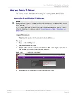
How to Configure Reference Clock for Chassis Synchronization
1
Configure Chassis Clock Source (refer to section titled “Configure Clock
2
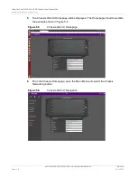
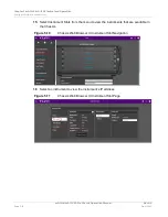
Navigate to the Sync Routing Diagram of the Chassis Web UI.
–
Access: Main Menu > Sync Diagram
3
Select the CLK100 Signal Relay Switch.
4
Configure the Sync Clock Divider.
Sync Trigger Input for Chassis Synchronization
This procedure provides instructions to configure a Chassis to use the Trigger Input Signal
for system synchronization. This procedure involves routing a signal from the Chassis
Trigger Input Connector to the Chassis internal trigger.
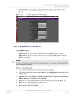
How to Configure Sync Trigger Input for Chassis Synchronization
1
Connect a valid input signal to Chassis Trigger Input Connector.
2
Configure Chassis Trigger Routing.
–
Main Menu > Triggers Diagram
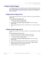
3
Select the
Click to Configure Trigger Routing Matrix
box from the Trigger
Diagrams page.
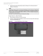
4
Navigate to the Sync Routing Diagram.
–
Main Menu > Sync Diagram
5
Select the SYNC_TRIG_OUT Signal Relay Switch.
NOTE
The Chassis synchronization signal can be driven by any applicable signal from the
Trigger Routing Matrix, not just the External Trigger Input Connector.
Summary of Contents for mA-1302
Page 1: ...mA 1302 mA 1305 AXIe Chassis Operation Manual ...
Page 3: ......