


5 — Configuring your system
Configuring your system
There are a number of items to do to get your system on your network and
ready to use.
Startup and shutdown
There are several procedures to turn on or off your system.
First plug in the power cord
1.
Plug the power cords into the rear of the power supplies.
2.
Wait until the blue Information LED starts to blink.
3.
Press the power button once. The control board initiates the power up
sequence in three seconds.
After normal shutdown by IPMI or power button
Press the power button once.
After a power loss
The system will power up automatically approximately fifteen seconds after
the power returns.
Power down
Turn off the unit using a clean operating system shutdown from Windows.
How to install the SFPs
This product uses hot-swappable SFPs, but you should disconnect any cables
before changing the SFP modules.
Caution:
Wear a grounding strap when handling SFPs to avoid
damaging them or other components. Avoid exposure to laser
radiation from optical components by keeping the dust plugs
installed until you are ready to install the cables.
♦
can be inserted into any open port and in any
order.
♦
You can hot-swap the connected transceivers at any time, but it is
recommended you then re-launch Observer Analyzer so that the
new speeds can be identified.
How to set the IP address
Set the IP address of the hardware appliance while you still have physical
access to it, such as immediately after it is racked and cabled. Setting the IP
address ensures the hardware appliance has a visible and permanent network
presence.
Prerequisite(s):
♦
switch or keyboard, monitor, and mouse are connected.
The user input devices or KVM switch are only temporarily
needed to set the IP address, so you can disconnect them after the
IP address is set.
♦
The IP, subnet, and gateway or router addresses are available and
known to you.
1.
Log in to the Windows operating system using the Administrator
account and its default password admin.
You can change the Administrator account password after logging in.
See the Windows documentation if necessary.
2.
In Windows, choose Start > Control Panel > Network and Sharing
Center > Change adapter settings.
3.
Right-click ETH0 and choose Properties.
4.
Select Internet Protocol Version 4 (TCP/IPv4), and click Properties.
5.
Set the IP address, subnet mask, router or gateway, and DNS server for
your environment and click OK.
6.
Click OK again to close the Properties dialog for that network
connection.
You interact with the hardware appliance through the Apex UI.
1.
Navigate to
https://hostname
where
hostname
is the IP
address or DNS name for the appliance.
2.
Log into the interface using the username
admin
and default password
admin.
Configuring the LOM or IPMI port
Your appliance comes with an on-board LOM or IPMI port that provides
you a dedicated management channel for device maintenance. It allows you
to monitor, start, stop, and manage your appliance remotely regardless of
whether the appliance is powered on.
Prerequisite(s):
♦
A GigaStor system.
♦
Keyboard, monitor, and mouse or KVM attached to the GigaStor.
♦
The static station IP, subnet, and gateway/router addresses are
available and known to you.
If you want to use Lights Out Management features, you must first configure
the IP address for the IPMI port from the BIOS. Then, you should change the
administrator password to something different than the default.
1.
Connect an Ethernet cable from your router or switch to the IPMI or
LOM port.
2.
When starting your appliance, press Delete during POST to enter the
BIOS setup.
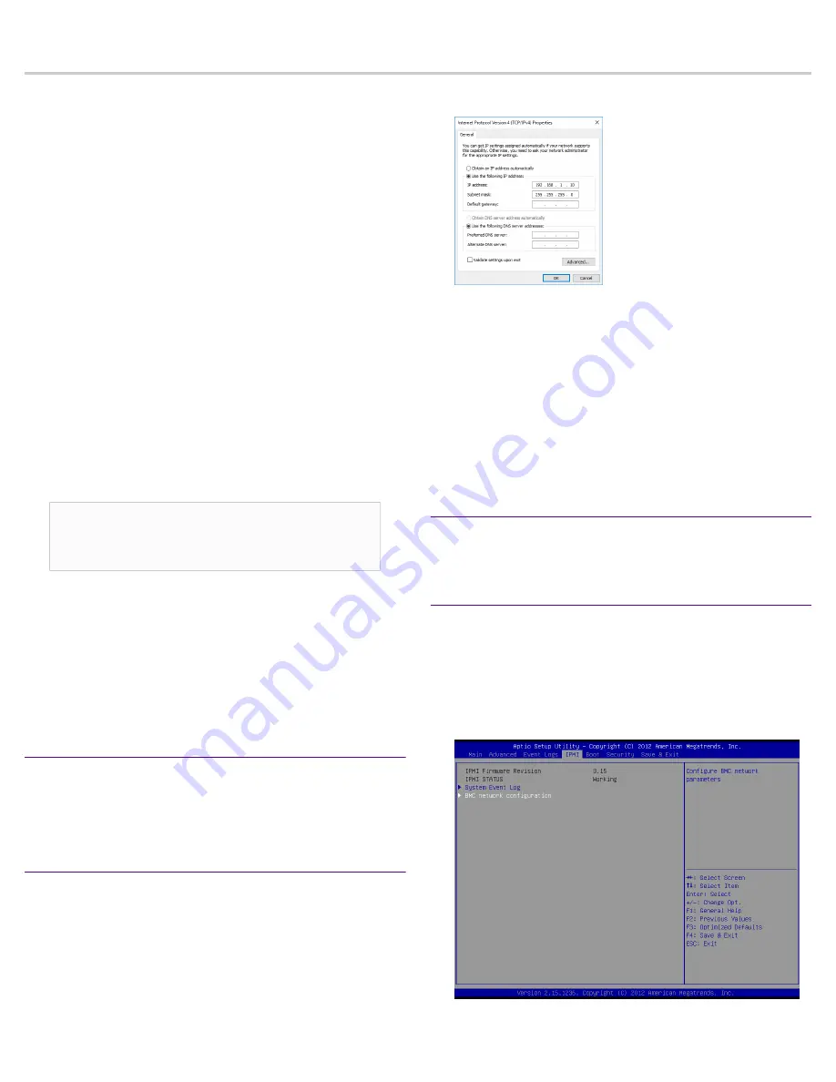
3.
In the BIOS, choose IPMI > BMC network configuration.
4.
Set Update IPMI LAN configuration to Yes.


