18
COM3 and COM4 ports
The VIPRO VP7815 provides two D-Sub 9-pin connectors on the
bottom I/O side, which offers standard RS-232 serial
communications interface.
Refer to the table list below for the pin assignments of COM3 and
COM4.
Pin Signal
1
DCD
2
RxD
3
TxD
4
DTR
5
GND
6
DSR
7
RTS
8
CTS
9
RI
LED Indicators
There are two LEDs on the VIPRO VP7815 bottom I/O side for
indicating system status:
• PWR LED
PWR LED
PWR LED
PWR LED is for power status and flashes in green
• HDD
HDD
HDD
HDD LED
LED
LED
LED is for hard disk and compact flash disk status, and
flashes in red.
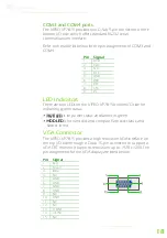
VGA Connector
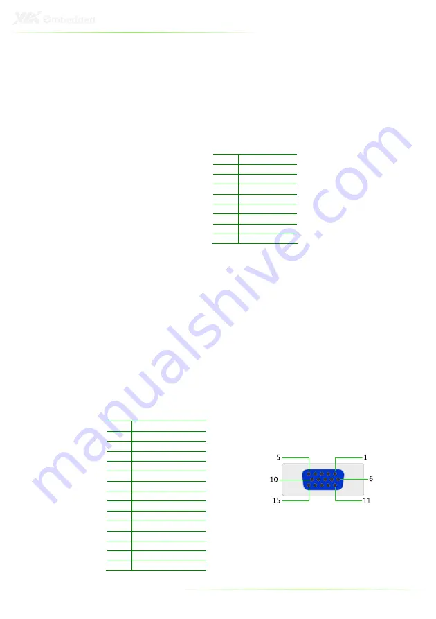
The VIPRO VP7815 provides a high resolution VGA interface on
the top I/O side through a D-sub 15-pin connector to support a
VGA CRT monitor. It supports resolutions up to 1920 x 1200. The
pin assignments for the VGA display are listed below.
Pin Signal
1
Red
2
Green
3
Blue
4
NC
5
GND
6
GND
7
GND
8
GND
9
NC
10
GND
11
NC
12
NC
13
H-SYNC
14
V-SYNC
15
NC
Summary of Contents for VIPRO VP7815
Page 10: ...X ...
Page 11: ...1 1 Product Overview ...
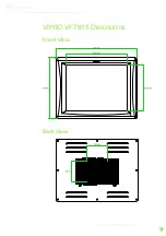
Page 19: ...9 VIPRO VP7815 DIMENSIONS Front View Back View ...
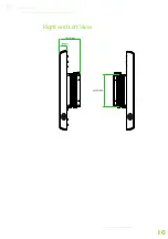
Page 20: ...10 Right and Left View ...
Page 22: ...12 Heatsink Grease Part 99G26 110022 ...
Page 24: ...14 INTRODUCTION OF I O LAYOUT Front View Layout Top View Layout ...
Page 25: ...15 Bottom View Layout Right and Left View Layout ...
Page 49: ...39 4 BIOS Setup This chapter gives a detailed explanation of the BIOS setup functions ...
Page 64: ...54 INTEGRATED PERIPHERALS ...


