Vexve BFC400F1 Installation, Operation And Maintenance Manual Download Page 13

12

13

www.vexve.com

www.vexve.com

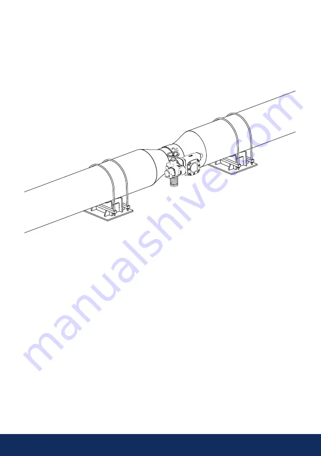
Figure 15. Pipeline supports.

4.3 Pipeline supports and pipeline reducers

 
Pipeline supports should not be installed under the valve!

If pipeline reducers are used in connection with the valve, additional pipeline supports must be used 
because of the higher mechanical load on the valve (see figure 15).

Summary of Contents for BFC400F1

Page 1: ...Butterfly valves Installation operation and maintenance manual ...

Page 2: ...lve with flanged connections 17 4 7 Before commissioning 18 4 8 Flushing 18 4 9 Commissioning 19 4 10 Pressure test 19 5 Actuator disassembly and installation 20 5 1 Removing the actuator 20 5 2 Changing the actuator installation position 21 5 3 Actuator installation 21 5 4 Electric actuator 21 5 5 Hydraulic actuator 21 5 6 Actuator installation positions 22 6 Maintenance 24 6 1 Replacing the stem...

Page 3: ...pply Vexve Oy requires that any faulty products under warranty are to be returned to the factory for inspection Only after the product has been found faulty Vexve Oy can grant compensa tion Please refer to Vexve Oy s General terms and conditions of sale for detailed warranty clauses The document is available from the manufacturer Warnings and symbols Ignoring the warnings and symbols may lead to s...

Page 4: ...alve can be used within the following temperature pressure range Please note that the maximum allowable working pressure is dependent on the operating temperature Chart 1 Pressure temperature chart Note DN 1200 1600 temperature range 20 200 C The maximum allowable work ing pressure is dependent on the operating temperature NOTE When intending to use the valve for other media or applications please...

Page 5: ...e identification plate are as follows 1 Valve manufacturer 2 Valve product number which is individual valve number 3 Valve type B butterfly valve 4 Product group F full bore R reduced bore 5 Valve use S shut off valve C control valve 6 Valve size DN 7 Connection to the pipeline W welding ends F flanged ends 8 Manufacturing year 9 Eurasian Conformity Valve Certification 10 CE marking and ID of the ...

Page 6: ...lve adjustments NOTE Take the weight of the valve into account when handling it When delivered the valve will be in the closed position During storage the valve must be lightly closed Maximum recommended storage time is two years If the valve is stored for more than two years it should be operated and cleaned yearly Packaging Vexve s products are protected during transpor tation with special packa...

Page 7: ...7 www vexve com Figure 4 Lifting a valve equipped with 4 lifting lugs Figure 3 Lifting a valve equipped with 2 lifting lugs Figure 5 Storage ...

Page 8: ...d dust and other impurities If the valve was delivered with the actuator installed avoid removing the actuator during installation Incorrect re installation or adjustment of the actuator will result in a high risk of damage and leakage Exercise extreme caution when testing the valve before installation in the pipeline The valve or valve assembly must not be lifted by the actuator If the valve is e...

Page 9: ...installation as any welding debris or other impurities can damage the valve Valve installation Check the instructions for the correct location of valve in the pipeline see chapter 4 1 Install the valve in an allowed position see chapter 4 2 See chapter 4 5 for installation instructions of valve with welding ends See chapter 4 6 for installation instructions of valve with flanges NOTE The valve mus...

Page 10: ...pipe connections Minimum installation distances shown in figure 9 should be followed 1 Pipe bend axis 2 Stem axis 3 Pump shaft axis Figure 9 Minimum distances D pipeline diameter Figure 10 Valve location NOTE Valve should not be installed in such sections in the pipeline where impurities can easily be piled For example lowest sections of the pipeline should be avoided see figure 10 ...

Page 11: ...hould be installed so that the stem axis is perpendicular to the pipe bend axis see figure 9 Especially a control butterfly valve should be installed after a centrifugal pump so that stem axis is at 90 angle in relation to the pump shaft axis see figure 9 However if two valves are installed one after the other the stems must be perpendicular to each other When installed this way the loading on the...

Page 12: ...n at an angle Figure 14 Not recommended positions 4 2 1 Installation in a horizontal pipeline The most recommendable installation position is in a horizontal pipeline with the valve stem horizontal see Figure 12 The valve can alternately be installed at an angle of max 45 see Figure 13 ...

Page 13: ...ne supports and pipeline reducers Pipeline supports should not be installed under the valve If pipeline reducers are used in connection with the valve additional pipeline supports must be used because of the higher mechanical load on the valve see figure 15 ...

Page 14: ... the valve must be filled with oxygen free water NOTE If the valve is located near to the blind flange at the end of the pipeline valve must not be fully closed Instead the valve must remain slightly open to prevent a closed space from forming between the valve and blind flange If water in the closed space expands for example due to temperature it may damage the valve Figure 17 Blank flange Min 45...

Page 15: ...flow direction is same as the recommended flow direction for the valve The recommended installation position for the valve is at an angle see Figure 19 or with the shafts in the horizontal position see Figure 18 Avoid installation with the shafts fully upright NOTE The greatest angle between stem axis and horizontal axis is 45 degrees see Figure 19 The valve must first be bridged to the pipeline u...

Page 16: ...commended method of welding the valve to the pipeline is welding with connection pipes see Figure 21 Tack welding and the welding order for the seams are the same as in Figures 18 and 19 Welding order 1 2 3 4 The valve must remain closed during installation and welding to ensure that welding residue does not damage the seal surfaces This also facilitates cleaning of the inner surfaces from welding...

Page 17: ...ndards The valve must remain closed during installation to ensure that any residue or dirt does not damage the sealing faces The sealing faces of the pipe flanges must be parallel to the valve sealing faces and correctly aligned The length of the valve must be the same as the distance between the flanges in the pipe line taking into consideration the gasket The flanges in the pipeline must be comp...

Page 18: ...3 To avoid pressure shocks and to reduce the forces caused by opening the valve under pres sure a by pass valve must be used in connection with butterfly valves see Figure 23 4 7 Before commissioning 4 8 Flushing Pipeline needs to be flushed carefully after the valve installation Before starting the flushing turn the valve disc so that the opening angle is 30 40 Close the valve gradually during th...

Page 19: ...greatest permitted test pressure against a closed valve is 1 1 x PN PN valve s max trim ΔP When carrying out a pipeline pressure test 1 5 x PN the valve must be fully open The tightness of the valve can be ensured after this If the stem is equipped with graphite packing BFC BRC models the tightness of the packing should be checked If required the graphite packings are tightened with the hexagonal ...

Page 20: ...re than 90 as this may damage the seal Due to the valve structure the disc can only be turned within its original range of 0 90 degrees 5 1 Removing the actuator Keep the valve and the pipeline non pressurised whenever the gearing is not connected In a butterfly valve the gear functions as a limiter for the open and close positions The valve itself is not equipped with limiters The manual gears us...

Page 21: ...n Make sure the valve is in the closed position Install the actuator such that the handwheel is in the desired direction Make sure that the stem is in the original position in relation to the actuator or that it is turned 180º Visually check that the actuator is straight in relation to the valve Fasten all mounting screws as tight as possible Set the mechanical limits for the closed position The o...

Page 22: ...ndwheel in relation to the flow direction seen from valve A side AR R Location of the handwheel on the right side AL L Location of the handwheel on the left side Actuator installation positions butterfly valve manual gear butterfly valve electric actuator Butterfly valve with actuator will be delivered in ABR position as a standard Please inform us whether you want to have another option when plac...

Page 23: ...23 www vexve com Figure 28 Installation position ABR Figure 30 Installation position ARA Figure 29 Installation position AAL Figure 31 Installation position ALB ...

Page 24: ...ity even when seldom used around ten times a year or less we recommend the following Approximately six months after commissioning and then once a year inspect the valve for for shaft leaks check the manual gear electric actuator hydraulic actuator and ensure the tightness of the screws between valves NOTE Impurities in the pipeline wear and damage caused by pressure shocks are the most common reas...

Page 25: ...act and clean it carefully Lubricate the O rings with for example Würth HHS2000 lubricant spray Replace the O rings on the O ring sleeve Check that there are no sharp edges on the place for the key groove elsewhere on the stem or on the stem sleeve as these could damage the O rings during installation Hone or tape over any sharp edges if necessary Push the O ring sleeve back in place We recommend ...

Page 26: ...needed for maintenance are available Keep the valve and the pipeline non pressurised whenever the gear is not connected Remove the actuator as instructed in chapter 5 Disconnect the key 8 from the stem 9 Remove the clamping bush 4 Remove the sliding bearing 5 Remove the sealing rings 6 Clean the shaft especially the area in contact with the clamping bush seals Install the new sealing rings Re inst...

Page 27: ...ng 1 pc 2 O ring sleeve 1 pc 3 Key 2 pcs 4 Identification plate 1 pc 5 Upper stem 1 pc 6 Cylindrical pin 3 pcs 7 Disc 1 pc 8 Disc seal 1 pc 9 Lower stem 1 pc 10 Lower stem bearing 1 pc 11 Safety ring 1 pc 12 Lower stem washer 1 pc 13 O ring 4 pcs 14 Upper stem bearing 1 pc 15 Valve body 1 pc 16 Positioner plate 1 pc 17 Sliding plate 1 pc 7 Appendices ...

Page 28: ...1 pc 5 Sliding bearing 1 pc 6 Stem seal 4 pc 7 Upper stem bearing 1 pc 8 Key 2 pcs 9 Upper stem 1 pc 10 Identification plate 1 pc 11 Cylindrical pin 3 pcs 12 Disc 1 pc 13 Disc seal 1 pc 14 Lower stem 1 pc 15 Lower stem bearing 1 pc 16 Lock ring 1 pc 17 Lower stem washer 1 pc 18 Actuator base 1 pc 19 Hexagonal nut 4 pcs 20 Washer 4 pcs 21 Hexagonal bolt 4 pcs 22 Valve body 1 pc 23 Positioner plate ...

Page 29: ...when not mentioned with weld connections according to EN DIN 8 E Special equipment note Typically valve equipped with electric actuator BFC BRC models also with manual gear Example BFS600W1 GS E Full bore shut off type DN 600 butterfly valve with GOST weld connections and electric actuator 1 2 3 4 5 6 7 8 B F S 600 W 1 GS E Example DN 400 Butterfly valve models BFS400W1 BFS400W1 E BFS400F1 BFS400F...

Page 30: ...14 2 x A 14x9x70 20 4xM20 F16 600 60 200 254 300 110 7 64 18 2 x A 18x11x100 25 8xM16 F25 700 70 200 254 300 110 7 74 5 20 2 x A 20x12x110 25 8xM16 F25 750 90 230 298 350 110 6 95 25 2 x A 25x14x110 40 8xM20 F30 800 90 230 298 350 110 6 95 25 2 x A 25x14x110 40 8xM20 F30 900 100 260 356 415 180 6 106 28 2 x A 28x16x160 40 8xM30 F35 1000 120 260 356 415 180 6 127 32 2 x A 32x18x160 40 8xM30 F35 120...

Page 31: ...14 2 x A 14x9x70 4xM20 F16 500 50 130 165 180 200 80 100 8 53 5 14 2 x A 14x9x70 4xM20 F16 600 60 200 254 270 300 110 100 8 64 18 2 x A 18x11x100 8xM16 F25 700 70 200 254 270 300 110 100 8 74 5 20 2 x A 20x12x110 8xM16 F25 750 90 230 298 350 400 130 120 10 95 25 2 x A 25x14x110 8xM20 F30 800 90 230 298 350 400 130 120 10 95 25 2 x A 25x14x110 8xM20 F30 900 100 260 356 400 450 180 150 12 5 106 28 2...

Page 32: ...Vexve Oy Pajakatu 11 38200 Sastamala Finland Tel 358 10 734 0800 vexve customer vexve com Riihenkalliontie 10 23800 Laitila Finland www vexve com 07 2020 All rights reserved ...

Reviews: