background image


10

/12


the middle wheel can zoom in and out of the graphics. At the same time, the content of the G-Code will be displayed 
in the lower command bar. During processing, the machine will run one by one according to the G-Code commands. 

 
(5).


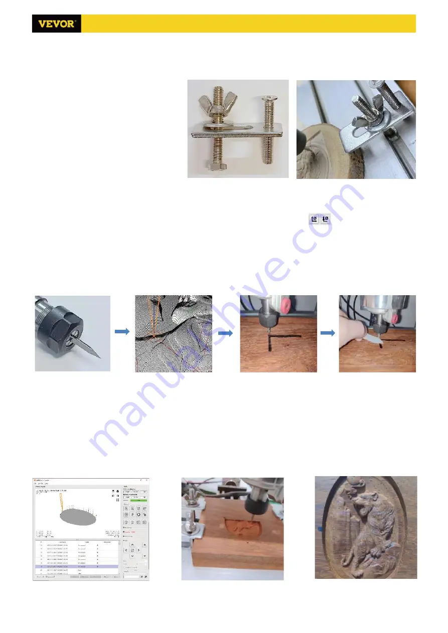
Fixture, tool installation and Set the working coordinate origin   


The fixture in the product kit is not 

assembled. There are four sets in total. The 
appearance and usage of the assembled 
fixture are shown in the right figures. 
    Before running the G code program, you 
need to find the position of the engraving 
figure relative to the overall engraving plate. 
There is a three-axis coordinate system in the 
visual graphics. The origin of the three-axis 
coordinate system is the tool setting point of 
the actual processing graphic.   
    You can move the tool to determine the position of the engraving graphic relative to the overall engraving plate 
based on the position of this origin. The engraving figure in the figure below is taken as an example. 
    After the selected tool position is started, the X/Y and Z axes are reset to zero (the 

  are zeroing X/Y and Z 

axes buttons). Before returning to zero, make sure that the tool approaches the distance of one sheet of paper for 
engraving, and then return the X/Y and Z axes to zero (please use a flat-bottom sharp knife when engraving, and use 
a cylindrical milling cutter when machining planes, slots, and holes) The effect is that the sculpted figure will be carved 
with the blade tip as the origin. 
    The ER11 collet on the spindle motor should be clamped into the fixed head first, and it must be clamped in place. 
When installing the cutter, please do not extend the collet too much, as shown in the first figure below. 


(6) Start carving


    After finding the engraving position, click the send button below and the device will automatically start engraving. 
The status bar at the top right shows running. The visualization window shows that the tool is moving along the tool 
path. You can choose the pause and stop buttons below when engraving. (After pausing, click again to continue the 
previous carving. After termination, click Send to start processing from the beginning). 

(7). Finished processing 

    After the processing is completed, the visualization window prompts that the engraving is completed and the time 
required for carving. 


Summary of Contents for S3018 Prover

Page 1: ...wn steps first cut off the power then pull out the USB cable Precautions 1 All parts description just for illustrative purpose If there is any difference please refer to the actual part shape 2 Please make sure that the machine is under care when it is working 3 If your machine is equipped with an offline controller please note that the offline controller and the computer cannot be connected to th...

Page 2: ...ssembled 4 G9 Self tapping screw M2 6 8 Already assembled 2 Part No Part Name Explanation Quantity Picture G10 Self tapping screw M2 6 6 Already assembled 4 9 1 Pressing plate 50 20 3 4 G11 Shim Already assembled 2 9 2 Screw M6 40 4 G12 Z1 Z2 Limit wire 2 0 2 54 Length 600mm 2 9 3 Screw M6 45 4 G13 X Y2 Limit wire 2 54 3P Length 600mm 2 9 4 Butterfly nut M6 4 G14 Y1 Limit wire 2 54 3P Length 300mm...

Page 3: ...3 12 X axis and Y axis component assembly 1 X axis component 1Set 4 Trapezoidal nut M5 20 8PCS 3 M5 16 8PCS 3018 Prover Ver V1 2 2 Machine Assembly 2 Y axis component 1Set ...

Page 4: ...4 12 Control board and emergency stop switch assembly C3 Ship nut M5 10 4PCS C1 Control board 1PCS C2 M5 12 4PCS G1 Emergency stop switch 1Set 3018 Prover Ver V1 2 ...

Page 5: ...5 12 Y limit switch and rubber mat assembly 6 Trapezoidal nut M4 20 4PCS 7 Rubber mat 4PCS 5 M4 10 4PCS G11 Shim 2PCS G3 Y limit switch 2PCS G8 M3 6 4PCS 3018 Prover Ver V1 2 ...

Page 6: ...6 12 Guard plate assembly D1 Guard plate 2PCS C3 Ship nut M5 10 8PCS D2 M5 10 8PCS 3018 Prover Ver V1 2 ...

Page 7: ... Y1 Axis X Axis Spindle Motor 24V Power 48V Spindle Motor 0 500W Power 24V DC USB Emergency Stop X Limit Z Axis Y1 Axis Y1 Limit Y2 Limit X Axis Spindle Motor Z1 Limit Z2 Limit 7 12 3018 Prover Ver V1 2 2 0 2 54 Length 600mm 2 0 2 54 Length 600mm 2 54 3P Length 300mm 2 54 3P Length 600mm 2 54 3P Length 600mm 2P Length 480mm 4P Length 480mm 4P Length 150mm 4P Length 480mm ...

Page 8: ...and blocks all G code commands 3 2 Control Home button Starts the homing cycle procedure with H command Z probe Starts the zero Z axis search procedure using the command specified in the settings Z probe commands box Example command G91G21 G38 2Z 30F100 G0Z1 G38 2Z 1F10 Zero X Y Zeroes the X and Y coordinates in the local coordinate system Also retains an local system offset G92 for later use Rest...

Page 9: ... rate click Finish The status bar at the top right of the Candle interface will show Idle and at the same time the console at the bottom right will display the information shown below indicating that the connection has been successfully established 4 Processing documents Click File option at the top of candle then click New to create G Code On the command bar at the bottom of the interface click O...

Page 10: ...reset to zero the are zeroing X Y and Z axes buttons Before returning to zero make sure that the tool approaches the distance of one sheet of paper for engraving and then return the X Y and Z axes to zero please use a flat bottom sharp knife when engraving and use a cylindrical milling cutter when machining planes slots and holes The effect is that the sculpted figure will be carved with the blade...

Page 11: ... 0 1 1 5 10 cycles each time Function 2 Press and hold for about 2 seconds to exit 4 3 File page File list Select the file to be engraved Support documents include NC NCC TAP TXT Gcode GCO NL CUT CNC Y up Y down OK SPN Confirm the selection and enter the confirmation engraving page 4 4 Confirm the engraving page Confirm that the engraving file is started without errors OK SPN Confirmation starts r...

Page 12: ...tuck or the stepper motor does not move please try to restore the factory settings of the main board The recovery method is as follows Method 1 Go to our website www VevorEngraver com to download VigoWorks software For Windows and run it Click the button Connect After the software connected the machine successfully click Settings On the settings window Click Restore Factory button then reboot the ...

Reviews: